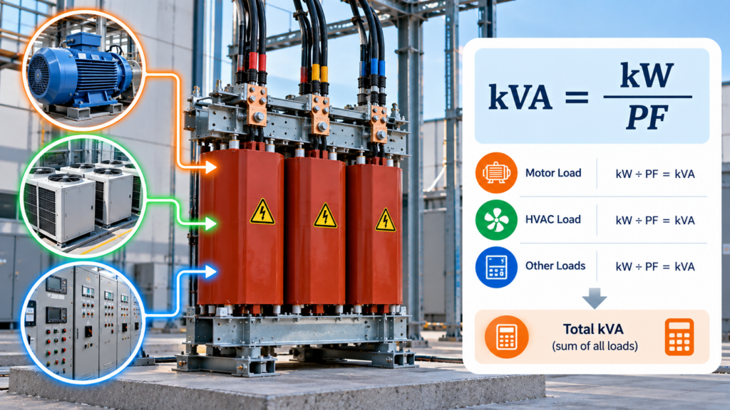
Transformer sizing starts with one number: kVA. Get the kVA right and the transformer will run within its design limits for decades. Get it wrong and the consequences show up as overheating, accelerated insulation aging, or — in the opposite direction — wasted capital on capacity that never gets used.
The math itself is straightforward. Where most sizing errors happen isn’t in the calculation; it’s in mixing up single-phase and three-phase formulas, confusing line-to-line and line-to-neutral voltages, or stopping at the calculated number instead of accounting for the real-world factors that drive it higher. This article walks through the formulas, the worked examples, and the considerations that come after.
Why Transformers Are Rated in kVA, Not kW
kVA (kilovolt-amperes) is apparent power — the total power the transformer must actually carry, including both the real power that does useful work (kW) and the reactive power that supports magnetic fields in motors, transformers, and other inductive loads (kVAR).
Transformer heating is driven by voltage, current, and impedance. Power factor doesn’t enter the heating equation directly, which is why transformers are rated in kVA rather than kW. A transformer feeding a 50 kW load at 0.8 power factor has to handle the same current as one feeding a 62.5 kW load at unity power factor — and it’s the current that produces the heat.
This is why every sizing calculation works in kVA, and conversions from kW require accounting for power factor.
Single-Phase kVA Calculation
For single-phase systems:
Where V is voltage in volts and I is current in amperes. Dividing by 1,000 converts VA to kVA.
Example. A 240 V load drawing 100 A:
A transformer supplying this load must be rated at at least 24 kVA. In practice this would round up to the next standard size — typically 25 kVA for single-phase.
Three-Phase kVA Calculation
Three-phase systems carry power across three conductors, so the formula includes a √3 factor to account for the phase relationship:
Where V is line-to-line voltage, I is line current, and √3 ≈ 1.732.
Example. A 480 V three-phase load drawing 75 A:
Round up to the next standard size — 75 kVA in this case.
The most common error here is using line-to-neutral voltage (for example, 277 V on a 480Y/277 V system) instead of line-to-line. The formula assumes line-to-line; using line-to-neutral will produce a number that’s too low by a factor of √3 and undersize the transformer significantly.
Converting from kW to kVA
When the load is specified in real power (kW) and power factor is known:
Example. A load requiring 50 kW at 0.8 power factor:
Round up to the next standard size.
This conversion matters whenever load data comes from equipment nameplates or mechanical/electrical schedules that report kW rather than kVA. Motors in particular are typically specified in horsepower or kW with a separate power factor figure.
Sizing from Existing Equipment
When working from nameplate data on existing equipment, the process is the same calculation applied to the data on hand:
- Identify system type — single-phase or three-phase
- Confirm the voltage rating, and verify whether it’s line-to-line or line-to-neutral
- Read or measure the full-load current
- Apply the correct formula
The result is the load’s actual kVA demand. From there, transformer sizing follows.
Why Accurate Sizing Matters
The cost of getting kVA wrong shows up at both extremes.
Undersizing drives overheating, accelerated insulation aging, voltage drop under load, nuisance tripping, and ultimately premature failure. Transformer insulation life roughly halves for every 8°C of sustained operation above the rated temperature rise, so even modest chronic overload has a real and measurable cost.
Oversizing costs less in failure terms but more in capital and operating efficiency. Larger transformers carry higher no-load losses, which run continuously whether the transformer is loaded or not. They also tend to operate at a lower fraction of their rated capacity, where efficiency curves are less favorable. The unit costs more to buy, more to install, and slightly more to run.
The goal is to size the transformer to load the actual demand, plus appropriate margin for the factors below.
Beyond the Calculation
The kVA number is the starting point, not the answer. Several factors push the required size up:
- Ambient temperature above the standard 40°C rating reduces capacity
- Altitude above 1,000 m (3,300 ft) reduces capacity due to thinner air cooling less effectively
- Harmonic content from variable frequency drives, UPS systems, LED drivers, and switching power supplies adds losses that linear kVA doesn’t capture
- Future load growth should be planned for explicitly rather than discovered later
- Duty cycle — continuous loads stress the transformer differently than intermittent ones
- Impedance requirements driven by short-circuit and protection coordination
- Inrush current from motor starting or transformer energization
For harmonic-rich environments, a K-factor transformer (K-4, K-13, or higher depending on the load profile) may be required even when the linear kVA calculation is correct. This is not a substitute for proper sizing — it’s an additional specification on top of it.
Standard Transformer Sizes
After calculating required kVA, select the next standard size above the calculated value:
- Three-phase: 15, 30, 45, 75, 112.5, 150, 225, 300, 500, 750, 1000 kVA, and higher
- Single-phase: 5, 7.5, 15, 25, 37.5, 50, 75, 100, 167, 250, 333, 500 kVA, and higher
Selecting the next standard size up is the conservative default. A detailed engineering study can sometimes justify tighter margins, but that’s the exception rather than the rule.
Conclusion
Calculating kVA is straightforward arithmetic. Sizing a transformer correctly is calculation plus judgment — applying the right formula to clean inputs, then adjusting for the environmental and load factors that shift the answer in practice.
Most sizing errors trace back to one of three causes: using the wrong formula for the system type, confusing line-to-line and line-to-neutral voltages, or treating the calculated number as the final answer without accounting for harmonics, ambient conditions, or future load. When those three are handled cleanly, the transformer runs within its design limits and delivers the service life it was built for.