Distribution Basse Tension
Autotransformateurs

Distribution Basse Tension
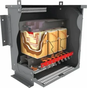
Rex Power Magnetics Autotransformers provide efficient and cost-effective voltage transformation for a wide range of industrial, commercial, and utility applications. By sharing common windings between the primary and secondary circuits, these transformers offer a compact and lightweight solution for applications where electrical isolation is not required but precise voltage adjustment and reliable performance are essential.
Engineered for high efficiency and excellent voltage regulation, Rex Autotransformers are ideal for motor starting, voltage correction, equipment interconnection, and system balancing applications. Each unit is designed with premium core materials, precision-wound conductors, and high-quality insulation systems to ensure dependable operation and long service life under continuous or intermittent load conditions.
Available in a wide range of kVA ratings, voltage configurations, and enclosure types, Rex Autotransformers are manufactured and tested to meet or exceed CSA and UL standards. Standard and custom designs are available to suit specific electrical and mechanical requirements — delivering reliable, efficient performance backed by Rex Power Magnetics’ proven engineering expertise.
| Capacity |
|
| Voltage Class | 1.2kV |
| Cooling | Air Cooled (ANN / AN) |
| Frequency | 60Hz (50/60Hz Optional) |
| Conductors | Copper (Cu) or Aluminum (Al) Windings |
| Temperature Rise | 150°C Rise (115°C or 80°C Optional) |
| Insulation System | 220°C |
| Impregnation | Polyester Resin Dipped and Baked |
| Sound Level | Meets NEMA ST-20 |
| Enclosure Type | Type 1 or 3R Indoor (Refer To Catalog) |
| Enclosure Finish | ANSI/ASA 61 Grey |
| Warranty | 12 Months (See Warranty and Limitations) |
| Quality System | ISO 9001:2015 Quality Management System |
| Certifications |
|
| Reference Standards |
|
| Optional Features & Accessories |
|
Distribution Transformer Catalog (English)
Distribution Transformer Catalog (French)
Maintenance, Operating & Installation Manual (English)
Maintenance, Operating & Installation Manual (French)
Distribution Transformer Catalog (English)
Distribution Transformer Catalog (French)
Maintenance, Operating & Installation Manual (English)
Maintenance, Operating & Installation Manual (French)
Product Guide Specification (English)
A Rex autotransformer uses a single winding per phase, divided into two electrical sections. The common winding is shared by the input and output circuits, while the series winding carries the voltage difference between them. For a 600 V to 480 V step-down application, the series winding spans 120 V and the common winding spans 480 V. The series winding carries the full input current, while the common winding carries the difference between input and output currents.
Because only part of the electrical power is transformed electromagnetically, an autotransformer requires less winding material and a smaller core than an equivalent general purpose isolation transformer. For example, a 150 kVA, 600 V to 480 V autotransformer transforms approximately 30 kVA electromagnetically while delivering the full 150 kVA to the load. This is known as the equivalent two-winding kVA, which determines the core and winding requirements.
The nameplate kVA represents the load capacity at the output voltage, not the equivalent two-winding kVA. When ordering, specify the required load kVA, input and output voltages, and operating conditions through the Product Configurator. If a project requires the equivalent kVA, request this figure from Rex to ensure the specifications and documentation agree.
For more information, see What Is an Autotransformer? and Understanding Transformer Nameplates
The primary difference is in winding configuration. An isolation transformer has separate primary and secondary windings, ensuring full electrical isolation, while an autotransformer uses a single shared winding with multiple taps. This design reduces size, weight, and losses, offering greater efficiency and lower cost. However, because the circuits are not isolated, autotransformers are typically used where system grounding and safety measures are well-controlled. Rex Power Magnetics engineers design each autotransformer to meet specific application and voltage ratio requirements while maintaining electrical reliability.
An autotransformer is a single-winding transformer that provides voltage transformation through tapped sections of a common winding. Unlike a two-winding isolation transformer, it does not provide electrical isolation between the primary and secondary circuits. Instead, it offers a compact, efficient solution for applications requiring voltage step-up or step-down within the same system. Rex Power Magnetics autotransformers are used in motor starting, voltage conversion, and equipment designed to operate on non-standard supply voltages where isolation is not required.
It`s normal for new transformers to release some harmless odors from the varnish impregnation used in the coils for a week or two after energization. Older Transformers can also release some odor if loaded to a higher level than they have experienced previously in their history.
A Rex autotransformer generally has lower impedance than a comparable two-winding isolation transformer because only part of the electrical power is transformed electromagnetically. The effective impedance depends on the voltage ratio, kVA rating, and winding design.
Lower impedance provides good voltage regulation, with relatively little output voltage change between no-load and full-load operation. However, it also means an autotransformer provides less limitation of available short-circuit current than an isolation transformer of comparable load capacity.
When specifying an autotransformer, the available fault current at the output must be evaluated to confirm that downstream equipment has adequate short-circuit ratings. Rex can provide the design impedance required for protection and fault-current studies.
See Transformer Impedance: Key Concepts and Calculations for more information.
A three-phase Rex autotransformer is normally connected in wye: the three windings meet at a common point, and the input and output taps are taken along each phase. The common point is the neutral of both the 600 V and the 480 V systems at once. With the N option, that point is brought out to a terminal so it can be connected to the supply neutral.
Specify N in three situations. When the 480 V equipment needs a 480Y/277 V four-wire supply, the output neutral can only be the supply neutral carried through. When the supply is 600Y/347 V solidly grounded and the load is unbalanced, connecting the common point to the supply neutral fixes the phase-to-neutral voltages on the output; left floating, an unbalanced load shifts the neutral point and the output phase voltages become unequal. And when code rules require a grounded conductor to be solidly connected to the autotransformer for the circuit it supplies, the N terminal is where that connection is made.
The neutral terminal is a connection point, not a new grounding point. Because the output is not a separately derived system, the neutral is not bonded to the enclosure at the autotransformer; system bonding remains at the service. Transformer Grounding and Bonding Explained sets out the distinction, and Wye vs. Delta: Connection Choices discusses neutral behaviour.
Rex autotransformers use a 220°C insulation system with a standard 150°C average winding temperature rise. The optional T115 and T80 configurations reduce the permitted temperature rise to 115°C and 80°C, respectively.
Lower temperature-rise designs generally require additional conductor and core material, increasing the transformer’s size, weight, and cost. However, they can provide additional thermal margin, reduce operating temperatures, and support applications with demanding environmental or loading conditions.
The appropriate temperature-rise rating depends on the expected load, ambient temperature, duty cycle, and installation environment. See Transformer Insulation Classes for additional information.
Each autotransformer is built using high-grade silicon steel cores and precision-wound copper or aluminum conductors. The core and coil assembly is dipped in polyester resin, which provides mechanical rigidity, improved insulation, and protection against moisture and contaminants. This process enhances durability and minimizes vibration and noise. Units are available as open core-and-coil assemblies or enclosed in NEMA-rated housings. Every transformer undergoes thorough electrical testing for performance, ratio accuracy, and dielectric strength before shipment.
Rex Power Magnetics’ ventilated distribution transformer terminals are rated 90°C. Conductors with at least a 90°C insulation rating at or below their 90°C ampacity rating should be utilized.
Temperature rise refers to average increase of temperature of the transformer windings at full load above the ambient temperature. when operating at full load. In addition to the average temperature rise of the windings, transformers also experience a « hot spot » temperature, which refers to the highest temperature point in the windings.
For example, a transformer with a 220°C insulation system may be designed with a 150°C average temperature rise and a 30°C hot spot allowance. This means that Above a 40C ambient, the total absolute temperature will not exceed 220°C. Transformers with lower temperature insulation systems (180°C or 200°C) will be designed with lower temperature rises (115° or 130°C) and hot spots so they can be installed in the same ambient temperature and still not exceed the temperature rating of the insulation system.
The table below shows the maximum average winding temperature rise, maximum hot spot temperature rise and maximum winding temperature for the most common insulation classes. Note that these are based on a max average ambient of 30°C during any 24-hour period and a maximum ambient of 40°C at any time.
| Insulation Class | Insulation Class | Average Winding Temperature Rise |
Hot Spot Temperature Rise |
Maximum Winding Temperature |
| Class 180 | F | 115°C | 145°C | 180°C |
| Class 200 | N | 130°C | 160°C | 200°C |
| Class 220 | H | 150°C | 180°C | 220°C |
Customers occasionally specify a transformer of a particular insulation class to be designed with an average temperature rise below the average temperature rise values shown in the table above. The benefits of doing so include:
Unless designed for special service conditions / environments, below are the standard service conditions for dry type distribution transformers:
To ensure proper operation, avoid installing transformers in environments with excessive moisture, extreme temperatures, or direct sunlight. Maintain recommended clearances and keep all ventilation panels unobstructed.
A three-phase Rex autotransformer is wound in wye, with the three common points joined. On a 600Y/347 V solidly grounded supply, the neutral point is fixed by connecting it to the supply neutral through the N terminal, or left internal on a three-wire unit where the load is balanced. The 480 V output is then a 480Y/277 V system referenced to the supply neutral.
On a 600 V three-wire delta supply, or a corner-grounded delta, there is no supply neutral to connect. The autotransformer’s wye point floats at whatever potential the phase voltages and load balance dictate. Under balanced load the output is a proper 480 V three-wire system; under unbalanced load, or when a ground fault on the delta system shifts the phase voltages, the floating point moves and the output voltages become unequal. The 480 V output is also ungrounded, which the equipment manufacturer may not accept.
Rex can build autotransformers for delta supplies, including delta-connected or open-delta arrangements for balanced three-wire loads, but the correct choice depends on the load and the grounding of the 600 V system. State the supply configuration and grounding on the enquiry. Where the load needs a grounded 480 V neutral and the supply cannot provide one, an isolation transformer is the only option. See Wye vs. Delta: Connection Choices and Transformer Grounding: Understanding the Importance.
Yes. Small corrections are where an autotransformer is most economical, because the transformed fraction is tiny. Rex builds these from 3 kVA single-phase and 5 kVA three-phase, wound directly for the required ratio.
The sizing arithmetic is the same as for any autotransformer. Take a 30 kVA, 240 V single-phase heating load on a supply that measures 208 V. The transformed fraction is (240 − 208) ÷ 240 = 13.3 percent, so the winding handles 30 × 0.133 = 4 kVA and the unit is physically a 4 kVA class coil. The output current is 30,000 ÷ 240 = 125 A, all of which passes through the series winding; the common winding carries only the 17 A difference. Order it as a 30 kVA, 208 V to 240 V single-phase autotransformer, and the nameplate will reflect the 30 kVA throughput.
For three-phase corrections such as 480 V to 460 V or 208 V to 220 V, the same rule applies per phase: a 100 kVA load corrected from 480 V to 460 V transforms only 4.2 kVA. Where the correction is below about 5 percent, first check whether the equipment’s own tolerance already covers it. Where the correction must be adjustable, add the W1 tap option. Use the Calculators on the Rex site to check the currents, and How to Calculate Transformer Load for the load side.
Most DC fast chargers are built for a 480Y/277 V three-phase input, while Canadian commercial services are commonly 600Y/347 V. A Rex autotransformer is a compact way to bridge that gap, and it is widely used on EV charging sites where the charger manufacturer does not require isolation. Because only 20 percent of the charging power is transformed, a 600 kVA charging hub can be served by an autotransformer with the losses and footprint of a 120 kVA class unit, which matters for a site running near continuously.
Several details govern whether the autotransformer is the right choice. Chargers generally require a solidly grounded wye supply with a neutral or defined ground reference for their input EMC filters and ground-fault monitoring, so specify the N option and connect it to the 600 V service neutral. Chargers are rectifier loads; check the manufacturer’s harmonic data and specify K4 or higher. In many cases, these autotransformers are specified with a 4 or 5 legged core construction to allow for phase loss detection. Outdoor pad-mounted installations call for the E3R or E4X enclosure and, in a cold climate, anti-condensation heaters. Sizing should use the aggregate continuous charger input rating, since chargers can run at full output for hours, and leave room for future stalls.
Some charger manufacturers, and some utilities, require an isolation transformer on the charger supply; in that case use a general purpose isolation transformer instead. Transformer Considerations for EV Charging Infrastructure covers the wider site design.
Yes. A Rex autotransformer can operate in either direction, converting 600 V to 480 V or stepping 480 V up to 600 V when its ratings and connection arrangements permit. This makes it suitable for equipment interconnection and system balancing applications, such as connecting a 480 V generator, battery inverter or energy storage power conversion system to a 600 V plant bus.
Because only the voltage difference is transformed electromagnetically, an autotransformer is smaller and has lower losses than an equivalent isolation transformer. For example, a 500 kVA, 480 V to 600 V interconnection transforms approximately 100 kVA electromagnetically while transferring the full 500 kVA. This can improve efficiency in energy storage systems where power flows in both directions.
Bidirectional applications require additional consideration of overcurrent protection, grounding arrangements and fault contributions from both the utility and connected equipment. If the unit includes the W1 tap option, the tap arrangement and voltage ratio must also be confirmed for reverse operation. Since an autotransformer does not provide galvanic isolation, the inverter or generator must be compatible with the existing system grounding, and any neutral-ground bonds must be properly coordinated.
When ordering, specify the bidirectional duty, input and output voltages, tap requirements, grounding configuration and expected harmonic loading. Where the equipment manufacturer or interconnection requirements specify electrical isolation, a general purpose isolation transformer may be required.
For additional guidance, see Step-Up Dry-Type Transformers and Transformer Grounding and Bonding Explained .
Autotransformers are used for adjusting supply voltages in power distribution systems, controlling motor starting currents, and converting equipment for use on alternate voltage systems. They are also applied in test benches, variable voltage supplies, and energy management systems. In industrial settings, autotransformers are often used to match equipment designed for 480 V operation to 600 V supply systems. Their compact design and high efficiency make them ideal for both fixed and adjustable voltage control applications.
In dry-type transformers, the surrounding air plays a critical role in their operation. Generally, low ambient temperatures do not negatively impact an energized transformer, as the no-load losses typically generate enough heat to maintain proper conditions, even in environments as cold as -30°C. However, transformers stored at low temperatures present two primary concerns:
Rex Power Magnetics recommends testing transformers (megger testing), warming them to above 0°C, or following a drying-out procedure if moisture is suspected. Refer to Rex Power Magnetics’ cold start procedures to ensure safe energization in cold conditions. Energizing a transformer with compromised insulation due to moisture can cause damage and potential safety hazards.
The minimum required clearances of a dry type transformer to walls, floors or other equipment must adhere to the local electrical code requirements.
In the absence of such requirements, Rex Power Magnetics recommends that dry type transformers be mounted so that there is an air space of no less than 150mm (6”) between the enclosures, and between the enclosure and any adjacent surface except floors. When the adjacent surface is a combustible material, the minimum permissible separation between the transformer enclosure and the adjacent surface should be 300mm (12”). Where the adjacent surface is the wall on which the transformer is mounted, the minimum permissible separation between the enclosure and the mounting wall should be 6mm (0.25”) so long as the surface is of a non-combustible material.
Any transformer which is not installed and energized immediately should be stored in a dry, clean space having a uniform temperature to prevent condensation on the windings. Dry type transformers with resin dipped or epoxy vacuum impregnated coils can be stored at ambient temperatures as low as -50C. Transformers with encapsulated or epoxy cast coils should not be stored at ambient temperatures below -20C to prevent cracking of the epoxy. Preferably, transformers should be stored in a heated building having adequate air circulation and protected from cement, plaster, paint, dirt, and water or other gases, powders, and dust. The floor on which the transformer is being stored should be resistant to the upward migration of water vapor. Precautions should be taken to prevent storage in an area that water could be present, such as roof leaks, windows, etc. Condensation or absorption of moisture can be greatly reduced by keeping the transformer enclosure 5⁰C-10⁰C above ambient temperature. This can be easily achieved by the installation and energization of space heaters (optional). If the transformer is not furnished with internal space heaters, then external, portable heaters can be used. Note: Lamps or heaters should never come in direct contact with the transformer coil insulation.
It is not advisable to store a dry type transformer outdoors, but in the case that it is unavoidable, protective measures should be taken to prevent moisture and foreign debris from entering the transformer enclosure. The plastic wrapping supplied during shipment should be left in place, and a suitable drying agent such as silica gel packs should be used. The unit should also be checked periodically for indications of condensation on the windings, coil support blocks, core, core clamping system and bus/cables.
Rex autotransformers are built to meet the NEMA ST-20 sound-level limits, the same standard applied across the low voltage distribution range. The audible hum of a dry-type transformer comes from magnetostriction in the core steel and electromagnetic forces on the coils, and both scale with the size of the core and the flux it carries. Because a Rex autotransformer’s core is sized for the equivalent two-winding kVA, a 300 kVA, 600 V to 480 V unit has the core of a 60 kVA class transformer and, broadly, its sound level, which is several decibels below the ST-20 figure for a 300 kVA two-winding unit.
The applicable NEMA ST-20 limit is the one for the transformer’s equivalent kVA class; ask Rex for the guaranteed value if the unit is going into a noise-sensitive space such as an office, laboratory or data centre electrical room. Installed noise also depends on the mounting, and the Y1 external anti-vibration pads are the first defence against structure-borne transmission through a wall or steel frame.
Noise that rises after installation usually points to a cause outside the transformer: supply voltage above nominal, which overexcites the core; DC offset or harmonics in the load current; loose enclosure panels; or a floating neutral point on a delta supply allowing phase voltages to shift. Transformer Humming Noise: Causes and Ways to Reduce It works through the diagnostic sequence.
Size on the running load, but check the starting condition. A Rex autotransformer is a continuous-duty device rated in kVA, and the thermal design assumes the nameplate load. A motor starting across the line draws six to eight times full-load current for a few seconds; the coil’s thermal mass absorbs that without meaningful temperature rise, so starting does not require a larger transformer.
Take a 50 HP, 460 V motor with a full-load current of 65 A, started direct-on-line from a 600 V supply through a 600 V to 480 V autotransformer. Running kVA is 1.732 × 480 × 65 ÷ 1,000 = 54 kVA, so a 75 kVA unit gives a comfortable margin and room for a second smaller motor. Locked-rotor current of about 420 A flows during acceleration. The check that matters is voltage dip: with autotransformer impedance of the order of 1 percent on the throughput base, the drop across the transformer at 420 A on a 75 kVA unit (90 A rated) is roughly 1 percent × (420 ÷ 90) = 4.7 percent, acceptable for most motors; the supply impedance usually contributes more.
This is a different problem from reduced-voltage starting, for which Rex builds the short-time-rated motor starting autotransformer. How Is Transformer kVA Calculated? covers the load calculation.
Inrush occurs when a transformer is energized at a point on the voltage wave that drives the core into saturation. In a Rex autotransformer, the core is sized for the equivalent two-winding kVA, which for a 600 V to 480 V unit is 20 percent of the throughput. The inrush the core can draw is therefore that of a much smaller transformer. Expressed as a multiple of full-load input current, which is set by the throughput kVA, the inrush of a 600 V to 480 V autotransformer is typically a small fraction of what a two-winding unit of the same load kVA would draw.
For the protection engineer this means the input breaker or fuses, sized at up to 125 percent of full-load input current under the autotransformer rules, are rarely troubled by inrush, and nuisance tripping on energization is uncommon. The exception is a high-ratio autotransformer, such as 600 V to 208 V, where the core is sized for 65 percent of the throughput and inrush approaches that of an isolation transformer.
If the autotransformer is energized together with its load, the load’s own inrush, such as capacitor charging in a drive or charger, adds to it and is usually the larger term. Transformer Inrush Current Explained covers the mechanism and reduction techniques.
Yes. Because they use a single winding, autotransformers are inherently more efficient than isolation transformers. Efficiency often exceeds 97%, resulting in lower operating costs and reduced heat generation. The reduced copper and core material requirements contribute to compact size and improved performance. Rex Power Magnetics designs its autotransformers to deliver stable voltage regulation and minimal losses, making them an environmentally and economically advantageous choice where isolation is not required.
Autotransformers provide significant savings in material, size, and cost compared to isolation transformers of equivalent capacity. They offer higher efficiency due to reduced winding losses and better voltage regulation under load. Their compact construction simplifies installation, especially in retrofit applications. Because only part of the winding handles full load current, autotransformers deliver more kVA per pound of material, making them an efficient choice when electrical isolation is not a requirement.
The life expectancy of a dry-type transformer is primarily determined by the insulation system and the operating temperature. According to IEEE Std. C57.96, the deterioration of insulation is directly related to the time and temperature the transformer experiences during operation. Insulation materials degrade faster at higher temperatures, so the transformer’s life expectancy is closely tied to how well it is kept within its design temperature limits.
In most transformers, the highest temperature occurs at a specific point in the windings, known as the hot spot. This area undergoes the most significant wear over time, making it the primary factor in determining the transformer’s ageing process.
All of Rex Power Magnetics’ dry-type transformers are designed using UL-listed insulation systems with a maximum hot spot temperature that ensures a design life of at least 30 years under standard operating conditions (continuous rated load, typical ambient temperatures, and no sustained overloads). Transformers designed with reduced temperature rise can extend this design life expectancy to over 50 years, as operating at lower temperatures slows the insulation’s ageing process.
Factors That Affect Life Expectancy:
By following proper installation and maintenance practices, such as avoiding overloading and ensuring the transformer operates within its designed ambient temperature, you can significantly extend its lifespan. Rex Power Magnetics’ high-quality transformers are built for durability, ensuring reliable performance for decades under standard conditions.
Commissioning follows the general dry-type checks in the installation manual, with several items specific to the shared-winding construction.
• Confirm the nameplate ratio, kVA, input and output voltages against the drawings, and verify the tap position if the W1 option was supplied.
• Insulation-resistance test the entire winding to ground and core. There is no winding-to-winding test on an autotransformer, so this single reading is the whole dielectric check.
• Verify that the supply neutral, if the unit has the N option, is connected to the neutral terminal, and that there is no neutral-to-ground bond at the autotransformer or anywhere on the output side.
• Verify phase rotation and phasing at the output terminals against the supply.
• Confirm the input overcurrent device rating against the full-load input current, and that no device has been placed in the common winding.
• Check that the 480 V equipment’s short-circuit current rating is adequate for the fault current that will pass through.
• If the unit has been stored or transported in cold or damp conditions, follow the Cold Start Procedure before energizing.
Energize at no load, read the output voltage on all phases and to neutral, and only then connect the load. Transformer Commissioning: Critical Checks for Safe Energization expands each step, and Low-Ambient Temperature Considerations covers the cold-weather case.
Start with the load current, measured on the output conductors with the load running. Because the nameplate kVA is the throughput at the output voltage, output current above kVA ÷ (1.732 × V_out) means the unit is overloaded, however small it looks. Overloading is common on autotransformers because their size understates their rating.
If the current is within rating, check its waveform. A K1 unit feeding a K9 drive or charger load runs hot well below nameplate current; the remedy is a K-rated replacement or load reduction. Next, check the supply voltage: above-nominal supply, common on 600 V systems at light plant load, overexcites the core and raises no-load loss and temperature; use the W1 tap if fitted. Then check for blocked ventilation, an ambient above 40°C, or a non-ventilated enclosure applied without derating.
Voltage sag under load usually points to something other than the transformer, because the autotransformer’s own regulation is only about 1 percent. If the input voltage sags at the same moment, the supply feeder is the cause. If the input holds, check for a loose or high-resistance tap or terminal connection, which also produces localized heating, and check the neutral connection on an unbalanced load with the N option, since a lost neutral shifts phase voltages. Rex can advise on a replacement through Contact. Transformer Maintenance: Essential Checklist lists the measurements to trend.
Rex Power Magnetics provides extensive customization capabilities for autotransformers. Options include specific voltage ratios, kVA ratings, taps, and enclosure types to match customer requirements. Custom-engineered units can be designed for harmonic conditions, continuous or intermittent duty, or specialized environmental protection. Engineering support is available to assist OEMs and system integrators in designing transformers that meet precise technical and mechanical specifications. All custom units are built and tested to the same rigorous standards as catalog models.