Distribution Basse Tension
Transformateurs d’isolement à usage général

Distribution Basse Tension
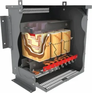
Rex Power Magnetics General Purpose Isolation Transformers provide safe, reliable voltage transformation and electrical isolation for a wide range of commercial, industrial, and institutional applications. Designed to protect sensitive equipment and enhance system safety, these transformers isolate primary and secondary circuits, minimizing electrical noise, transient disturbances, and the risk of shock or ground loops.
Built using high-grade core steel, precision-wound copper or aluminum conductors, and robust insulation systems, each transformer delivers excellent voltage regulation, low losses, and long service life. Dry-type construction ensures safe, low-maintenance operation, while optional electrostatic shielding further reduces line-to-line and line-to-ground noise transmission.
Available in a broad range of kVA ratings and voltage configurations, Rex General Purpose Isolation Transformers are designed and tested to meet or exceed CSA and UL standards. Standard and custom-engineered models are offered to accommodate unique voltage combinations, environmental conditions, and installation requirements — delivering dependable performance and long-term reliability for virtually any electrical system.
| Capacity |
|
| Voltage Class | 1.2kV |
| Cooling | Self Cooled (ANN / AN) |
| Frequency | 60Hz (50/60Hz Optional) |
| Conductors | Copper (Cu) or Aluminum (Al) Windings |
| Temperature Rise | 150°C rise (115°C or 80°C Optional) |
| Insulation System | 220°C |
| Impregnation | Polyester Resin Dipped and Baked |
| Efficiency | Meets North American Energy Efficiency Standards:
|
| Primary Taps | Typically +/-2 x 2.5% taps (refer to dry type distribution transformer catalogue) |
| Sound Level | Meets NEMA ST-20 |
| Enclosure Type | Type 1 or 3R Indoor (refer to catalog) |
| Enclosure Finish | ANSI/ASA 61 Grey |
| Warranty | 12 Months (See Warranty and Limitations) |
| Quality System | ISO 9001:2015 Quality Management System |
| Certifications |
|
| Reference Standards |
|
| Optional Features |
|
Distribution Transformer Catalog (English)
Distribution Transformer Catalog (French)
Maintenance, Operating & Installation Manual (English)
Maintenance, Operating & Installation Manual (French)
Configure a general purpose isolation transformer to build its Rex catalog part number. Codes follow the Rex catalog numbering system.
NRCan / DOE (Z3) levels are not available for Type 4 / 4X enclosures.
Selecting a K-factor rating of K4 or higher makes this a K-Factor Rated Isolation transformer — a different product line built for non-linear (harmonic) loads. The part number is assembled correctly either way; for K-rated units you may prefer the dedicated K-Factor Rated Isolation configurator.
This tool assembles a catalog part number from the options you select, following the Rex Power Magnetics catalog numbering system. Not every combination of options is necessarily a standard or available product, and some configurations may require review or a custom quote. For a voltage not listed, the code ‘X’ is used and the value specified separately. Rex Power Magnetics makes no representations as to the accuracy of the information generated by this tool; part numbers should be confirmed with Rex before ordering. Contact Rex Power Magnetics to verify availability, pricing, and specifications.
A ground loop forms when two pieces of equipment share a signal reference but are grounded at different points, so the potential difference between those points drives current along the signal shield. A general purpose isolation transformer breaks the loop at power frequency because the secondary is a separately derived system: its neutral and ground reference are established at the transformer, so the instrument rack is no longer tied to a remote ground through its supply conductors. That part needs no shield. What the two-winding construction does not remove is high-frequency common-mode noise coupled through the interwinding capacitance, which is why Rex designs these units with low interwinding capacitance and offers a grounded electrostatic shield (codes S1, S2, S3) as an option. For a lighting panel, no shield is needed. For instrumentation, laboratory or communications loads, specify at least a single shield and bond the shield lead to the enclosure ground pad at the same point as the system bonding jumper, never at a remote panel. See How Electrostatic Shields Reduce Transformer Noise and the Power Quality industry page.
No. A general purpose isolation transformer transfers power at the same frequency and, for a delta-delta or wye-wye connection, the same phase relationship as the supply; a delta-wye connection introduces the standard 30° displacement between primary and secondary line voltages, but nothing about the waveform frequency changes. The standard design is 60 Hz. The 50/60 Hz option (builder code 50) is not a switch; it is a core design change. Flux density in the core is proportional to volts per hertz, so a 60 Hz core connected to 50 Hz at the same voltage runs 20 percent higher in flux, which drives it toward saturation, raises magnetizing current, core loss, noise and temperature. A 50/60 Hz unit is built with enough core cross-section that it operates within limits at 50 Hz, and therefore runs conservatively at 60 Hz. Specify it for export equipment, marine installations that may connect to 50 Hz shore power, and test benches. Note that a 60 Hz unit operated at 50 Hz is outside its CSA and UL listing basis. The Marine Duty page discusses mixed-frequency supplies, and How Transformers Work covers the volts-per-hertz relationship.
A Mini Power Center packages a Rex core and coil with a primary main breaker and a secondary panelboard in one enclosure, whereas a general purpose isolation transformer is the transformer alone, wired by the installer to separate primary and secondary protection. Choose the mini power center when the load is a small, self-contained group of 120 V circuits at a remote location: a compressor house, a rooftop mechanical area, a temporary construction site, a pump station, or a machine cell where a 600 V or 480 V feeder is available but no 120 V panel is nearby. It saves the labour of mounting and wiring three separate pieces of equipment and gives a single listed assembly. Choose the stand-alone transformer when the kVA exceeds what the integrated package covers, when the secondary panel already exists or must be a specific manufacturer’s product, when the enclosure or mounting must match a switchgear lineup, or when the core and coil is going inside a customer enclosure as a C&C open unit. Both use the same resin-dipped construction, so environmental and thermal behaviour is identical. The Mini Power Centers Explained article and the Temporary Power page give typical examples.
A standard general purpose isolation transformer is certified for ordinary locations. It is a ventilated device with open louvres and, in normal operation, no arcing parts; however, its winding surface temperature under load and the possibility of a fault inside the enclosure mean it does not carry a classified-area rating, and the authority having jurisdiction will not accept it in a Class I, Division 1 or Division 2 area on its own. Both the CEC and the NEC allow transformers in Division 2 locations only when they are of a type suitable for the location or are installed in a vault or other arrangement that meets the classified-area rules. Rex’s Hazardous Location Transformer range in the Specialty Products category is designed for those areas, with construction and temperature codes matched to the gas group. The usual engineering answer is to locate the general purpose unit outside the classified boundary, in an unclassified electrical room, and run the secondary feeder into the area with approved wiring methods, which keeps the transformer a standard catalogue item. Where that is impossible, for example in a compact mining process module, the hazardous location design is the route. State the area classification on the quote request so Rex assigns the correct product.
The standard general purpose isolation transformer is built to a K1 (non-K-rated) design, which assumes the load current is essentially sinusoidal: incandescent, fluorescent and LED lighting with reasonable driver quality, resistive heating, general receptacles, HVAC fan and pump motors started across the line, machine tool motors, and control systems. A load stops being « general purpose » when a significant share of its current is drawn through rectifiers: VFDs, UPS inputs, DC power supplies for server racks, high-density LED driver banks, or EV charger power modules. The practical threshold Rex uses at quotation is the measured or estimated K-factor of the combined load. If it stays at or below about K4, the general purpose design carries it; above that, the winding eddy losses climb faster than the nameplate accounts for and the unit should be ordered K-rated (K4 through K30 are available on this product) or replaced with a K-Factor Rated Transformer. A single dedicated drive is better served by a Drive Isolation Transformer. The Knowledge Hub’s What Is an Isolation Transformer? article covers the base application set.
These transformers are used wherever voltage conversion and electrical isolation are required. Common applications include lighting panels, machine tools, control systems, HVAC equipment, and building power distribution. They are also widely used for powering instrumentation and electronic equipment requiring clean, stable voltage. Rex Power Magnetics general purpose isolation transformers are suitable for both OEM equipment and facility installations, delivering dependable performance in a wide variety of environments and load conditions.
Electrical isolation prevents a direct electrical path between source and load circuits, protecting personnel and equipment from electrical shock and transient disturbances. It minimizes the effects of ground loops, harmonics, and high-frequency noise that can interfere with sensitive equipment. In automation and control systems, isolation enhances signal integrity and system reliability. Rex Power Magnetics designs its transformers with high dielectric insulation and low interwinding capacitance to maximize electrical separation while maintaining energy efficiency and quiet performance.
A general purpose isolation transformer transfers electrical power between circuits while providing complete galvanic isolation between the primary and secondary windings. This isolation helps protect connected loads from electrical noise, transients, and faults on the supply side. The transformer maintains the same frequency and phase while converting voltage levels as needed. Rex Power Magnetics general purpose isolation transformers are designed for reliable operation in commercial, institutional, and light industrial environments where electrical safety and voltage stability are essential.
It`s normal for new transformers to release some harmless odors from the varnish impregnation used in the coils for a week or two after energization. Older Transformers can also release some odor if loaded to a higher level than they have experienced previously in their history.
The standard general purpose isolation transformer has two 2.5 percent full-capacity taps above and two below nominal on the primary. The W1 special-feature code changes that to six taps: two 2.5 percent full-capacity above normal (FCAN) and four 2.5 percent full-capacity below normal (FCBN). On the terminal board that gives:
• 600 V primary, standard: 630, 615, 600, 585, 570 V.
• 600 V primary, W1: 630, 615, 600, 585, 570, 555, 540 V.
• 480 V primary, standard: 504, 492, 480, 468, 456 V.
• 480 V primary, W1: 504, 492, 480, 468, 456, 444, 432 V.
Because the taps are full-capacity, the transformer delivers its nameplate kVA on any of them, but primary current increases in proportion on the low taps: a 112.5 kVA unit on the 540 V tap draws 120 A instead of 108 A, which should be reflected in the primary overcurrent setting. Taps are changed de-energized by moving the primary lead on the terminal board, not by a switch. W1 suits sites at the end of long rural feeders in Ontario and the Prairies that run chronically low, and EV charging depots where high daytime load depresses the service voltage. The Transformer Tap Changers article explains full-capacity versus reduced-capacity taps, and the Calculators page checks the resulting ratio.
Rex lists the general purpose isolation transformer as meeting U.S. DOE 10 CFR Part 431 (DOE 2016) and Canada’s SOR/2018-201 Amendment 14 with Ontario Regulation 404/12 (NRCan 2019), which Rex codes as efficiency level Z3 in the Part Number Builder. Both regimes use the same minimum efficiency table for low voltage dry-type distribution transformers, evaluated at 35 percent of nameplate load and a reference winding temperature. The 35 percent test point was chosen because field surveys show distribution transformers spend most of their life lightly loaded, so no-load core loss dominates lifetime energy. A compliant design therefore uses more and better core steel, which lowers core loss at every load but tends to raise magnetizing inrush and size. Rex supplies the guaranteed loss and efficiency values for a specific rating on the test report and can quote a custom level (code ZX) where a project wants lower losses than the mandated floor. The Energy-Efficient Low Voltage Transformers article compares the regimes; DOE 2029 covers the next step.
Rex offers three levels of temperature monitoring on the general purpose isolation transformer.
• Thermal sensing and indication embeds sensors (typically RTDs or thermistors) in the hottest region of each coil, where the hot spot forms, and brings the leads to a terminal strip for a building management system or a temperature monitor.
• Thermometers, analog or digital, give a local reading for commissioning and thermographic surveys and can be wired to a building monitoring system (BMS)
• Thermostat alarm/trip provides fixed-setpoint switches with N.O. and N.C. contacts, usually one stage for alarm and a second, higher stage for trip. The setpoints are chosen relative to the 150°C rise and 220°C insulation system so that the alarm operates when the winding is approaching its continuous limit and the trip operates before the hot spot reaches the insulation rating; Rex sets them for the specific rise ordered, so a 115°C or 80°C unit gets lower setpoints.
For a data centre or hospital, monitoring is normally mandatory, and it is inexpensive insurance on any unit above 150 kVA.
Strip heaters are listed as an option on the general purpose isolation transformer and are worth specifying whenever the unit will sit de-energized in an environment where the air temperature swings across the dew point: outdoor Type 3R installations, unheated warehouses, pump stations, standby feeders that are energized only during outages, temporary power skids, and any transformer that will be stored on site for months before energization. An energized transformer keeps itself dry with its own no-load loss; a cold, idle one does not, and Rex’s storage guidance is to hold the enclosure interior 5 to 10°C above ambient to stop condensation on the coils. The heaters are low-wattage resistance elements mounted low in the enclosure, sized for the enclosure volume rather than the kVA, and supplied from a separate 120 V circuit. The correct control is either a thermostat or humidistat inside the enclosure or an interlock that runs the heaters only when the primary breaker is open, since they are unnecessary when the unit is loaded. The heater circuit must be on the drawing so the installer provides the auxiliary supply; it is often forgotten on outdoor units. Where the heaters were not ordered, Rex’s storage FAQ allows external portable heaters, provided they never contact the coil insulation. Follow the Transformer Cold Start Procedure before energizing a unit that has been cold, and see Low-Ambient Temperature Considerations.
Rex Power Magnetics’ ventilated distribution transformer terminals are rated 90°C. Conductors with at least a 90°C insulation rating at or below their 90°C ampacity rating should be utilized.
Temperature rise refers to average increase of temperature of the transformer windings at full load above the ambient temperature. when operating at full load. In addition to the average temperature rise of the windings, transformers also experience a « hot spot » temperature, which refers to the highest temperature point in the windings.
For example, a transformer with a 220°C insulation system may be designed with a 150°C average temperature rise and a 30°C hot spot allowance. This means that Above a 40C ambient, the total absolute temperature will not exceed 220°C. Transformers with lower temperature insulation systems (180°C or 200°C) will be designed with lower temperature rises (115° or 130°C) and hot spots so they can be installed in the same ambient temperature and still not exceed the temperature rating of the insulation system.
The table below shows the maximum average winding temperature rise, maximum hot spot temperature rise and maximum winding temperature for the most common insulation classes. Note that these are based on a max average ambient of 30°C during any 24-hour period and a maximum ambient of 40°C at any time.
| Insulation Class | Insulation Class | Average Winding Temperature Rise |
Hot Spot Temperature Rise |
Maximum Winding Temperature |
| Class 180 | F | 115°C | 145°C | 180°C |
| Class 200 | N | 130°C | 160°C | 200°C |
| Class 220 | H | 150°C | 180°C | 220°C |
Customers occasionally specify a transformer of a particular insulation class to be designed with an average temperature rise below the average temperature rise values shown in the table above. The benefits of doing so include:
Unless designed for special service conditions / environments, below are the standard service conditions for dry type distribution transformers:
To ensure proper operation, avoid installing transformers in environments with excessive moisture, extreme temperatures, or direct sunlight. Maintain recommended clearances and keep all ventilation panels unobstructed.
The standard three-phase general purpose isolation transformer for this ratio has a delta primary and a wye secondary. The delta primary is connected line-to-line (H1, H2, H3) and is indifferent to whether the source is a 600 V delta or a 600Y/347 V wye: it sees 600 V between phases in both cases. What must not be done is to bring the 600Y/347 V supply neutral to the transformer and connect it to anything; the delta primary has no neutral point, and the supply neutral is not carried through to the secondary. On the 208Y/120 V secondary, X0 is the new neutral, bonded to the enclosure through the system bonding jumper and connected to the grounding electrode conductor, and the secondary neutral and the supply neutral are never joined. If the source is a 600 V delta that is corner-grounded or ungrounded, the primary connection is unchanged, but the primary overcurrent device and the equipment grounding must suit that system, and the electrostatic shield, if fitted, is still bonded at the transformer. Every standard connection, including the H and X terminal marking and the 30° delta-wye displacement, is drawn in the three-phase electrical schematic and connection diagrams. Background on the connection choice is in 3-Phase Transformer Wiring: Connections & Diagrams and Transformer Grounding and Bonding Explained.
A single-phase general purpose isolation transformer with a 120/240 V secondary has its secondary winding brought out as X1, X2/X3 (the midpoint, connected together) and X4. The midpoint becomes the neutral of a three-wire separately derived system: it is bonded once to the enclosure and to the grounding electrode, and the two outer terminals feed the 240 V or the two 120 V legs. Loads should be balanced between the legs so that the neutral carries only the difference current.
If the installation needs 120 V only, do not simply use half the winding, because that halves the available kVA and leaves the unused half floating. Instead, connect the two halves in parallel (X1 to X3 and X2 to X4, observing the polarity marks on the diagram) to obtain a 120 V two-wire output at full kVA, and bond one terminal as the grounded conductor. The alternative is to order a 120 V single-voltage secondary from Rex.
All standard connections are in the single-phase schematic diagrams on the Documentation page. The Transformer Grounding: Understanding the Importance article covers the single bonding point rule.
Rex’s installation manual and the Transformer Commissioning article set out the sequence for a general purpose isolation transformer; the essential steps are:
• Inspect for shipping damage, remove packing and any shipping braces, and confirm the nameplate matches the drawing.
• Check that the unit has not been stored cold or damp; if it has, apply the Transformer Cold Start Procedure, including warming above 0°C.
• Measure insulation resistance primary-to-secondary, primary-to-ground and secondary-to-ground with a megger appropriate to the 600 V class, and record the values with the winding temperature as the baseline for future maintenance.
• Confirm the tap connection against the measured supply voltage and move it if the site runs high or low.
• Verify the secondary neutral bond, the grounding electrode conductor, the electrostatic shield ground (if fitted) and the equipment ground, and torque all terminal connections to the values on the drawing.
• Check phase rotation on the primary and the expected 30° displacement on a delta-wye unit.
• Energize with the secondary breaker open, listen and check secondary voltages line-to-line and line-to-neutral, then apply load in steps and read currents on all phases and the neutral.
Record everything on the commissioning sheet; the megger baseline is what makes later readings meaningful. Rex’s factory ratio and dielectric test results are on file for the serial number.
Yes, and it is done where a single unit is too large for the room or the door, or where redundancy is required. For two general purpose isolation transformers to share load without circulating current, the following must match:
• primary and secondary voltage ratings
• the tap in use on each unit (both on the same tap, checked at commissioning)
• the winding connection and phase displacement, so a delta-wye unit cannot be paralleled with a delta-delta unit
• polarity and phase sequence at the paralleling point
• per-unit impedance, which by convention should be within about 7.5 percent of each other, or the lower-impedance unit takes more than its share.
Because impedance depends on the specific design, the cleanest approach is to order both units together and ask Rex to match them. If a new unit is being paralleled with an existing one, send the existing nameplate and test report so the new unit can be designed to the same impedance. Each transformer needs its own primary protection and, where the code requires it, its own secondary device before the tie. The neutral is bonded once for the combined system. Verify load sharing with clamp readings at commissioning. Full treatment is in Transformer Paralleling: Principles and Practical Considerations and Transformer Impedance.
Level 2 AC chargers in Canada are typically 208 V or 240 V single-phase devices grouped on a 208Y/120 V panel, so a 600 V delta to 208Y/120 V general purpose isolation transformer is the usual interface. Points to build into the specification:
• size on the coincident demand allowed by the load management system, not the sum of charger nameplates, and then add growth, since most depots double within a few years
• each charger’s onboard rectifier draws harmonic current, so specify K4 as a minimum and ask Rex to review the charger data for K9 on dense installations
• order an electrostatic shield (S1) to keep charger switching noise off the building supply
• specify a 200 percent neutral if the load is dominated by single-phase chargers
• use 115°C rise where the depot runs at full load for long evening periods and where a 30-plus year life is expected
• for an outdoor pad, a Type 3R (E3R) enclosure
• The W1 extended low taps are useful where the service voltage sags under charging load.
DC fast chargers at 480 V on a 600 V service are a different case that may require a step-up or custom ratio. The Transformer Considerations for EV Charging Infrastructure article is the starting point.
A general purpose isolation transformer on generator supply behaves the same electrically, but the source is weaker and the environment harsher. Generator subtransient reactance is much higher than a utility service, so the transformer’s magnetizing inrush produces a larger voltage dip at the generator terminals and can trip the generator’s own protection or stall its voltage regulator; the fix is to size the generator with inrush in mind, energize the transformer before other large loads, and, on skids that are switched frequently, consider a lower-flux design or a unit at 115°C rise, both of which reduce the inrush multiple. Generator voltage regulation is also looser, so the W1 extended taps or at least attention to the tap setting keeps secondary voltage in range. For the skid itself, specify a Type 3R (E3R) or Type 4 enclosure, anti-vibration pads (Y1) to protect the core and coil from transport shock, strip heaters for unheated storage between jobs, and copper windings where the unit will be moved often, since copper terminations tolerate repeated re-torquing better. Grounding is the item most often wrong on temporary installations: the secondary is still a separately derived system and needs its own bonding jumper and electrode connection at the skid, coordinated with the generator’s neutral grounding. The Temporary Power industry page and the Transformer Inrush Current article cover the details.
Yes. When supplied with NEMA 3R or higher-rated enclosures, these transformers are suitable for outdoor or damp environments. The polyester resin coating protects the core and windings from moisture, dust, and corrosion, while the weatherproof housing shields electrical connections. For more severe environments, encapsulated construction or stainless-steel enclosures are available. Proper mounting, grounding, and ventilation practices must be followed to maintain performance and meet CSA and local electrical code requirements for outdoor installations.
Dry-type transformers can generally be connected in reverse (back-fed), but there are some precautions to consider:
Always review applicable codes and standards and consult with the local authority having jurisdiction before reverse feeding transformers.
In dry-type transformers, the surrounding air plays a critical role in their operation. Generally, low ambient temperatures do not negatively impact an energized transformer, as the no-load losses typically generate enough heat to maintain proper conditions, even in environments as cold as -30°C. However, transformers stored at low temperatures present two primary concerns:
Rex Power Magnetics recommends testing transformers (megger testing), warming them to above 0°C, or following a drying-out procedure if moisture is suspected. Refer to Rex Power Magnetics’ cold start procedures to ensure safe energization in cold conditions. Energizing a transformer with compromised insulation due to moisture can cause damage and potential safety hazards.
The minimum required clearances of a dry type transformer to walls, floors or other equipment must adhere to the local electrical code requirements.
In the absence of such requirements, Rex Power Magnetics recommends that dry type transformers be mounted so that there is an air space of no less than 150mm (6”) between the enclosures, and between the enclosure and any adjacent surface except floors. When the adjacent surface is a combustible material, the minimum permissible separation between the transformer enclosure and the adjacent surface should be 300mm (12”). Where the adjacent surface is the wall on which the transformer is mounted, the minimum permissible separation between the enclosure and the mounting wall should be 6mm (0.25”) so long as the surface is of a non-combustible material.
Any transformer which is not installed and energized immediately should be stored in a dry, clean space having a uniform temperature to prevent condensation on the windings. Dry type transformers with resin dipped or epoxy vacuum impregnated coils can be stored at ambient temperatures as low as -50C. Transformers with encapsulated or epoxy cast coils should not be stored at ambient temperatures below -20C to prevent cracking of the epoxy. Preferably, transformers should be stored in a heated building having adequate air circulation and protected from cement, plaster, paint, dirt, and water or other gases, powders, and dust. The floor on which the transformer is being stored should be resistant to the upward migration of water vapor. Precautions should be taken to prevent storage in an area that water could be present, such as roof leaks, windows, etc. Condensation or absorption of moisture can be greatly reduced by keeping the transformer enclosure 5⁰C-10⁰C above ambient temperature. This can be easily achieved by the installation and energization of space heaters (optional). If the transformer is not furnished with internal space heaters, then external, portable heaters can be used. Note: Lamps or heaters should never come in direct contact with the transformer coil insulation.
It is not advisable to store a dry type transformer outdoors, but in the case that it is unavoidable, protective measures should be taken to prevent moisture and foreign debris from entering the transformer enclosure. The plastic wrapping supplied during shipment should be left in place, and a suitable drying agent such as silica gel packs should be used. The unit should also be checked periodically for indications of condensation on the windings, coil support blocks, core, core clamping system and bus/cables.
Start from the panel schedule, not the panel bus rating. Suppose a 600 V to 208Y/120 V general purpose isolation transformer is to feed a 42-circuit panel with 18 kVA of LED lighting, 24 kVA of general receptacles, and 6 kVA of small motors and miscellaneous, a connected load of 48 kVA. Apply the code demand factors: lighting in a commercial building is treated as continuous, so 18 × 1.25 = 22.5 kVA; receptacle load above the first 10 kVA may be taken at 50 percent, giving 10 + 7 = 17 kVA; motors at 6 kVA. Design load is 45.5 kVA. Add a growth allowance appropriate to the building, say 25 percent, giving 57 kVA, and select the next standard rating, 75 kVA, from Rex’s range. Rated secondary current is 75,000 ÷ (1.732 × 208) = 208 A, comfortably above the 45.5 kVA design current of 126 A, and primary current is 72 A. Do not go to 112.5 kVA « to be safe »: under DOE 2016 and NRCan 2019 the unit will run at about 20 percent load, where no-load loss dominates, and the first cost, weight and inrush all increase. If LED drivers dominate the lighting, order K4. The Calculators page converts amps and volts to kVA, and the Knowledge Hub articles How Is Transformer kVA Calculated? and How to Calculate Transformer Load walk through the arithmetic.
This is the most common call on a replacement project, and the transformer is rarely at fault. A new general purpose isolation transformer built to the DOE 2016 / NRCan 2019 efficiency level has more and better core steel operating at lower flux density than a unit built 25 years ago. That cuts core loss, but low-loss steel has a higher residual flux and a sharper saturation knee, so when the breaker closes near a voltage zero the core saturates and the magnetizing inrush can reach 10 to 20 times rated current for the first half-cycle. Low-rise and K-rated units carry still more steel and behave similarly. The old breaker’s instantaneous element was set for the old transformer. The corrective steps are: confirm the primary device is sized per CEC Section 26 and NEC 450.3(B), which allow up to 125 percent (primary-only) or 250 percent (with secondary protection) precisely to accommodate inrush; raise the instantaneous setting or select a breaker with an adjustable or higher fixed magnetic trip; use time-delay fuses whose minimum-melt curve clears the 0.1 second inrush point; and avoid electronic breakers with fast instantaneous overrides unless they have an inrush restraint feature. Rex can supply the inrush characteristic for the design on request. See Transformer Inrush Current Explained and Transformer Fuse Sizing.
An alarm well below nameplate on a general purpose isolation transformer means the winding is hotter than the load alone explains. Work through the causes in order of likelihood. Ventilation: check that the louvres are clear, that the 150 mm (6 in) clearance is maintained, that nothing has been stacked against the enclosure, and that the room ambient is within Rex’s 30°C average and 40°C maximum; a 45°C mechanical room removes 15°C of the 150°C rise allowance. Harmonics: measure the load current spectrum. A K1 unit feeding a panel that has acquired VFDs, UPS or dense LED drivers since it was installed carries eddy losses it was not designed for, and the cure is a K-rated unit or an upstream Harmonic Mitigating Transformer. Unbalance: read all three phase currents and the neutral. One phase at 100 percent with the others at 40 percent gives a 60 percent average but an overloaded coil. Tap and voltage: a unit on the −5 percent tap with a supply that has since risen to nominal is over-excited, and the core runs hot at any load. Connections: a loose or corroded terminal generates local heat that conducts into the coil; a thermographic survey finds it quickly. Finally, verify the alarm setpoint matches the rise ordered. The Transformer Failures: Causes, Faults and Prevention article expands on each.
Rex general purpose isolation transformers are designed to meet NEMA ST-20 sound levels, which are verified under controlled conditions: rated voltage, no load, free-field mounting. Field installations exceed that figure for reasons that are almost always outside the core and coil. Check over-excitation first: the hum is magnetostriction in the core, and it rises steeply with flux, so a unit on the −2.5 percent tap with a supply at nominal, or a 600 V unit on a service running at 620 V, is audibly louder; move the tap. Harmonic current from non-linear loads excites the core at 300 and 420 Hz, producing a higher-pitched whine on top of the 120 Hz hum; that is a K-factor question rather than a mechanical one. Mechanical amplification is the next group: rigid conduit acting as a sound conductor, a loose enclosure panel or louvre buzzing at 120 Hz, mounting on a hollow wall, or missing anti-vibration pads (code Y1). DC offset from half-wave rectifier loads elsewhere on the system saturates the core asymmetrically and produces a buzz that comes and goes with that load. A sudden change in noise from a previously quiet unit, especially with a rise in temperature, warrants shutdown and inspection for a shorted turn or loose core clamping. Why Do Transformers Hum details the mechanisms; contact Rex through the Contact page if a mechanical fault is suspected.
A three-phase delta-wye general purpose isolation transformer is really three single-phase coils on a common core, each rated for one third of the nameplate. A 75 kVA unit can therefore supply 25 kVA line-to-neutral per phase at 120 V, or 120 A per coil, and no more, regardless of how lightly the other two coils are loaded. Panels of single-phase 120 V loads must be balanced across the three phases; the practical rule is to keep phase currents within 10 percent of each other, and to rebalance the panel when circuits are added. Unbalance costs capacity, since the transformer is limited by its most heavily loaded coil, and it also raises the neutral current, which on a linear load equals the vector difference of the phase currents and on a non-linear load includes the arithmetic sum of the triplen harmonics. Rex’s standard neutral is sized for full phase current; a 200 percent neutral can be ordered where single-phase electronic loads dominate. Large single-phase 208 V loads connected line-to-line, such as a 208 V heater or a bank of Level 2 chargers, load two coils at once and should be rotated across the phase pairs. For a single large single-phase load, a single-phase unit (to 350 kVA) is the correct product. The Transformer Rating Explained article covers per-phase capacity, and the Data Centers page describes balanced PDU layouts.
Usually not above K4, and often K1 is sufficient, but it depends on the mix. Modern LED drivers with active power factor correction draw a reasonably sinusoidal current; low-cost drivers and older electronic ballasts draw a peaked current rich in 3rd and 5th harmonics. Desktop computers, monitors and small power supplies on receptacle circuits are all rectifier loads, and a floor of them has a K-factor in the K4 to K9 range even though each is small. The consequence for a general purpose isolation transformer is twofold: extra winding heating, which the K rating addresses, and 3rd-harmonic neutral current, which the K rating does not address but a 200 percent neutral does. A practical approach for a new office or institutional building: order the lighting transformer at K1 if the drivers are specified with power factor correction and at K4 if not; order the receptacle transformer at K4 with a 200 percent neutral, or at K9 where workstation density is high; and where the building has many such transformers, compare the total against a Harmonic Mitigating Transformer, which cancels the triplens rather than tolerating them. Over-specifying K13 on a lighting panel adds material and cost without benefit. The K-Factor Transformer Explained article gives the calculation, and Rex will confirm the rating from a measured spectrum submitted through the Product Configurator.
The life expectancy of a dry-type transformer is primarily determined by the insulation system and the operating temperature. According to IEEE Std. C57.96, the deterioration of insulation is directly related to the time and temperature the transformer experiences during operation. Insulation materials degrade faster at higher temperatures, so the transformer’s life expectancy is closely tied to how well it is kept within its design temperature limits.
In most transformers, the highest temperature occurs at a specific point in the windings, known as the hot spot. This area undergoes the most significant wear over time, making it the primary factor in determining the transformer’s ageing process.
All of Rex Power Magnetics’ dry-type transformers are designed using UL-listed insulation systems with a maximum hot spot temperature that ensures a design life of at least 30 years under standard operating conditions (continuous rated load, typical ambient temperatures, and no sustained overloads). Transformers designed with reduced temperature rise can extend this design life expectancy to over 50 years, as operating at lower temperatures slows the insulation’s ageing process.
Factors That Affect Life Expectancy:
By following proper installation and maintenance practices, such as avoiding overloading and ensuring the transformer operates within its designed ambient temperature, you can significantly extend its lifespan. Rex Power Magnetics’ high-quality transformers are built for durability, ensuring reliable performance for decades under standard conditions.
Only in specific winding arrangements. Both the CEC and the NEC permit the primary device to serve as protection for the secondary conductors when the transformer has a single-phase two-wire secondary or a three-phase delta-delta three-wire secondary, and only where the primary device rating, multiplied by the primary-to-secondary voltage ratio, does not exceed the allowable ampacity of the secondary conductors. The logic is that in those two cases the secondary current is always a fixed ratio of primary current, so the primary device sees every secondary overload. That logic fails on a delta-wye four-wire secondary, which is the common general purpose isolation transformer connection for 208Y/120 V: a line-to-neutral overload on one secondary phase is spread across two primary phases at a lower ratio and may never reach the primary trip level. Those secondaries need their own overcurrent device, normally at 125 percent of rated secondary current, located within the length limits the tap rules allow from the transformer terminals (the 3 m / 10 ft and 7.5 m / 25 ft transformer secondary conductor rules in the NEC, and the corresponding CEC Section 26 rules). A single-phase 120/240 V three-wire secondary is also excluded from the primary-only allowance because of the neutral. The Transformer Fuse Sizing article walks through both codes; confirm the interpretation with the authority having jurisdiction.
The efficiency regulations cover a general purpose distribution transformer as defined in the regulation, and the Part Number Builder for the general purpose isolation transformer offers three efficiency selections: Z3 (NRCan 2019 / DOE 2016), ZX (custom) and Exempt. Exempt is not a free choice; it applies only where the transformer, by its construction or intended use, is one of the categories the regulations exclude. Under DOE 10 CFR Part 431, and by close alignment under NRCan, those categories include transformers with a tap range of 20 percent or more, transformers designed for a specific non-general-purpose duty such as drive isolation (rectifier) service, welding, testing, grounding or uninterruptible power supply use, autotransformers, and certain special-impedance and machine-tool designs. Voltage ratios outside the defined ranges and units above the covered kVA limits also fall outside. See Energy-Efficient Low Voltage Transformers for the regulatory background.
A Rex nameplate follows the marking requirements of CSA C22.2 No. 47 and IEEE C57.12.01. On a general purpose isolation transformer it states the catalogue number and serial number; kVA and phase; frequency; primary and secondary voltages and the connection (delta or wye) with the tap voltages and the terminal identification for each; rated currents; percent impedance at the reference temperature; insulation system temperature (220°C) and rated average winding rise (150°C, 115°C or 80°C); the K-factor where the unit is K-rated; cooling class (ANN/AN); enclosure type; the efficiency compliance marking for DOE 2016 / NRCan 2019 where applicable; the CSA and UL marks; the date of manufacture; and, where ordered, the electrostatic shield ground terminal and accessory data. For a protection study, the two numbers that matter are the percent impedance and the rated secondary current: dividing the second by the first (as a decimal) gives the maximum secondary fault contribution with an infinite source, which sets the interrupting rating of the downstream panel and the arc-flash calculation. The full-load loss and no-load loss are on the certified test report rather than the nameplate; request them from Rex by serial number. Custom markings are ordered with the M code. The Understanding Transformer Nameplates article shows an annotated example, and Transformer Impedance covers the fault current arithmetic.
Yes. Rex Power Magnetics offers fully customized general purpose isolation transformers tailored to customer requirements. Options include non-standard voltage ratios, kVA ratings, special impedance levels, and custom enclosures. Our engineering team can design transformers with enhanced shielding, harmonic mitigation, or specific thermal performance targets. Each custom-built unit is produced and tested to the same rigorous standards, ensuring full compliance with applicable codes and reliable integration into specialized systems.
These transformers are low-maintenance devices. Periodic inspections should include verifying terminal tightness, ensuring unobstructed ventilation, and checking for dirt, corrosion, or insulation discoloration. The polyester resin coating minimizes moisture absorption and mechanical movement, reducing long-term maintenance needs. In dusty or high-humidity environments, more frequent cleaning and visual checks are advisable. With routine inspections and proper loading, Rex Power Magnetics isolation transformers provide decades of dependable service.