IEEE 519 Harmonic Limits: Voltage, Current, and PCC Requirements
Updated: August 17th, 2026
A variable frequency drive can show high current total harmonic distortion at its input while the facility still meets Institute of Electrical and Electronics Engineers Standard 519 (IEEE 519). The reverse can also happen: a moderate current-distortion reading may produce unacceptable voltage distortion when the source is weak or a capacitor bank creates resonance.
The missing detail is the measurement point. IEEE 519 does not impose one total harmonic distortion limit on every drive, panel, transformer, or electronic load. It establishes steady-state voltage and current distortion goals at the user point of common coupling (PCC). The PCC, system short-circuit strength, demand load current, harmonic spectrum, and operating condition all affect the assessment.
This article explains what the measurements mean, how the principal IEEE 519 limits are applied, and what those limits imply for transformer and harmonic-mitigation design.

What Harmonic Current Does to the Electrical System
Harmonics are voltage or current components at integer multiples of the fundamental frequency. On a 60 Hz system, the third harmonic is 180 Hz, the fifth is 300 Hz, and the seventh is 420 Hz.
They are produced mainly by non-linear loads. A rectifier, switch-mode power supply, variable frequency drive, uninterruptible power supply, LED driver, or electric vehicle charger draws current in pulses rather than as a smooth sine wave. Those pulses contain harmonic components that flow through transformers, bus bars, cables, and the source impedance.
The load produces harmonic current. When that current flows through supply-system impedance, it creates harmonic voltage drop. A stronger system generally experiences less voltage distortion for the same injected harmonic current; a weaker system experiences more.
Higher-frequency components also increase winding eddy-current and stray losses in transformers. In four-wire systems, triplen harmonics such as the third, ninth, and fifteenth are zero-sequence components. They can add in the neutral instead of cancelling, creating substantial neutral current even when the three-phase fundamental load appears balanced. Transformer connections and winding arrangements therefore affect how these currents circulate and where their effects appear. The practical differences between common connections are discussed further in our article on wye vs. delta, discussing connection choices and what they mean in practice.
For more detail on harmonic heating, see our guide to understanding the k-factor of transformers and harmonics and to understanding losses in transformers.
Why the Point of Common Coupling Controls the Assessment
Measurements taken at the input of a drive or uninterruptible power supply describe that equipment and its local circuit. They do not, by themselves, establish IEEE 519 performance.
The correct PCC must be established from the system arrangement, utility requirements, and project documents before data is interpreted. In a simple service, it may be close to the service entrance. In a campus, industrial plant, or distributed-energy installation, the applicable interface may require more careful definition.
A high current total harmonic distortion value at a lightly loaded branch circuit can look severe while the total harmonic current at the PCC remains acceptable. Conversely, several individually acceptable loads can combine at the PCC and exceed an individual harmonic or total demand distortion limit.
IEEE confirms that its steady-state voltage and current distortion limits apply at the user PCC for facilities containing harmonic-producing loads.
THD, TDD, and Individual Harmonics Are Not Interchangeable

Total harmonic distortion (THD) compares the root-sum-square harmonic content with the fundamental component of the waveform. Voltage THD is commonly written as THD-V, while current THD may be written as THD-I.
Current THD can be misleading at light load. If the harmonic current remains present while the fundamental current falls, the percentage rises because the denominator is smaller. A high instantaneous current THD reading therefore does not automatically indicate a high harmonic contribution relative to the facility’s demand.
Total demand distortion (TDD) uses the maximum demand load current, IL, as the reference instead of the instantaneous fundamental current. This creates a more stable basis for current limits at the PCC. IL is not simply the transformer nameplate current or whatever current happens to be measured during a short site visit. The load basis should reflect the project’s demand calculation and operating profile.
Individual harmonic distortion (IHD) evaluates each harmonic order separately. A system can remain within its total TDD limit and still exceed the limit for the fifth, seventh, eleventh, or another individual harmonic. The spectrum must therefore be reviewed, not just the total value.
K-Factor is different again. It represents the transformer heating effect of a harmonic current spectrum. It helps determine whether a transformer is thermally suitable for the load, but it is not an IEEE 519 compliance measurement.
IEEE 519 Voltage Distortion Limits
IEEE 519-2022 is the active edition and supersedes IEEE 519-2014. Its steady-state limits apply at the user PCC; they are not universal limits for equipment terminals.
For the voltage classes most commonly encountered in low- and medium-voltage facilities, the principal limits are:
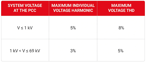
Tighter limits apply above 69 kV. The separate category for systems at or below 1 kV is important because it differs from the older practice of applying the 5% THD figure broadly to all systems below 69 kV.
An internal bus near a heavily distorted load may show a different value. Whether that value is acceptable depends on equipment capability and project criteria, even when the PCC remains within IEEE 519.
IEEE 519 Current Distortion Limits
Current limits depend partly on the ratio of available short-circuit current at the PCC, Isc, to maximum demand load current, IL. The ratio indicates system strength at that location.
A high Isc/IL ratio means the source is relatively stiff compared with the load. More harmonic current can flow before it produces the same voltage distortion. A low ratio indicates a weaker source, so the allowable current distortion is lower.
For systems from 120 V through 69 kV, the maximum TDD values are:
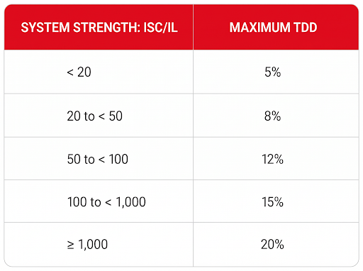
This is only the maximum TDD column. IEEE 519 also establishes limits for individual current harmonics according to harmonic order and system conditions. A complete study cannot use the table as a stand-alone pass-or-fail check.
Available short-circuit current must correspond to the applicable system condition and PCC. Transformer impedance, upstream source impedance, and system configuration affect the result. Explore our guides to transformer fault-current calculation and impedance in transformers for the underlying relationships.
How IEEE 519 Applies in Canadian Projects
IEEE 519 is widely used in Canadian power-quality studies, specifications, and utility interconnection requirements. It should not be described as a law that automatically applies to every installation.
CSA C22.1:24 is the 26th edition of the Canadian Electrical Code, Part I, an electrical-installation safety standard. Provinces and territories determine which edition and amendments have legal effect. IEEE 519 becomes a project requirement when it is incorporated through utility rules, connection agreements, engineering specifications, contracts, owner criteria, or requirements imposed by the authority having jurisdiction.
Hydro One’s March 2026 distributed-energy interconnection requirements provide one current example. The document applies harmonic requirements at the PCC and refers to IEEE 519 when an installation contains primarily harmonic-producing loads or a mixture of loads and inverter-based resources. That is a specific interconnection requirement, not a universal rule for every Canadian facility.
Before stating that a system complies with IEEE 519, confirm the governing document, PCC, measurement method, operating period, voltage class, short-circuit data, and acceptance limits.
Selecting the Correct Harmonic-Control Response
A harmonic solution should follow the measured problem. Selecting a K-Factor transformer, reactor, or filter from a single THD number can solve the wrong issue.
Establish Representative Operating Conditions
The study should capture voltage THD, current THD, TDD, individual harmonic magnitudes, demand loading, neutral current, transformer loading, available short-circuit current, and existing capacitor banks.
Trend data is usually more useful than one snapshot because drives, chargers, uninterruptible power supplies, and production equipment may operate differently by shift or process state. Measurements should represent the conditions under which the system is expected to meet its distortion targets.
Reduce Harmonic Current Near the Source
Line reactors, direct-current-link chokes, multi-pulse rectifiers, low-harmonic drives, active-front-end converters, and equipment with built-in correction can reduce current injected by individual loads. Their performance is load-dependent. A reactor that improves the current waveform of a six-pulse drive does not guarantee a particular TDD value at the PCC.
Where deeper attenuation is required, passive or active filters may be appropriate. Passive filters must be selected against the actual spectrum and system impedance. Their behaviour can change after a transformer replacement, capacitor-bank addition, or utility configuration change.
Explore line reactors vs. transient filters and passive harmonic filters for the differences between these devices.
Check Capacitor Banks for Resonance
Power-factor-correction capacitors and system inductance form a resonant circuit. If the resonant frequency lies near a dominant harmonic order, voltage and current can be amplified rather than reduced.
The result may be capacitor fuse operation, overheating, nuisance trips, or unexpectedly high voltage distortion. Capacitor banks should therefore be included in the harmonic model. Detuned banks, series reactors, filters, or a different compensation arrangement may be required.
Match the Transformer to the Objective
A K-Factor rated transformer is designed to carry a specified harmonic-rich load without exceeding its thermal limits. It addresses the consequence of harmonic current inside the transformer. It does not automatically reduce upstream harmonic current or establish IEEE 519 compliance.
A harmonic-mitigating transformer is intended to reduce selected harmonic components through engineered winding configurations, phase shifting, and, where applicable, zero-sequence harmonic treatment. Its performance depends on load balance, harmonic spectrum, transformer grouping, and phase-shift arrangement.
The two transformer types solve different problems. One manages the additional thermal duty. The other is intended to change the harmonic current presented to the upstream system.
Verify the Installed System
Repeat measurements should be taken at the same defined locations and under comparable operating conditions.
Verification should confirm the applicable voltage THD, TDD, and individual harmonic limits. It should also confirm neutral current, conductor loading, power factor, and transformer temperature. Acceptable PCC readings do not eliminate the need to verify that the transformer and connected conductors remain within their thermal ratings.
Conclusion
IEEE 519 is not a single THD limit, and it is not a transformer rating. It is a system-level framework for controlling steady-state voltage and current distortion at the user PCC.
The engineering decision begins with the correct measurement point and representative operating data. The voltage class, Isc/IL ratio, individual harmonic spectrum, system impedance, transformer loading, neutral current, and capacitor-bank interaction must then be considered together.
A K-Factor transformer can tolerate additional harmonic heating. A harmonic-mitigating transformer, reactor, or filter may reduce selected harmonic currents. None should be specified from a single instrument percentage. The equipment should be selected against the load spectrum, system strength, PCC target, and operating conditions the installation will actually see.
Transformer Failures: Causes, Warning Signs, and Prevention
Updated: August 17th, 2026
Transformers are designed for long, reliable service, but reliability does not come from the nameplate rating alone. A unit can be correctly manufactured and still fail prematurely if the load, installation, protection, or environment exposes it to stresses that were not considered in the original specification.
Most transformer failures also have more than one cause. A blocked ventilation path may raise winding temperature. The higher temperature accelerates insulation ageing. A later switching surge or short circuit then acts on insulation that has already lost part of its strength. The final event may appear to be the cause, even though deterioration had been developing for years.
Understanding that sequence allows asset owners to address the mechanism behind a warning sign rather than simply returning the unit to service after the immediate symptom disappears.

Why Dry-Type Transformers Fail
A transformer fails when one or more parts can no longer perform their electrical, thermal, or mechanical function. The result may be a winding short circuit, insulation flashover, overheated connection, core fault, unacceptable voltage performance, or protective-device operation.
Failure does not always mean a dramatic event. Insulation tracking, recurring temperature alarms, abnormal sound, or a terminal that repeatedly overheats can make a transformer unreliable before complete breakdown. These conditions are evidence to investigate, not independent maintenance problems.
Thermal Overstress and Insulation Ageing
Load current produces winding losses, while magnetic excitation produces core losses. Those losses become heat. Under the transformer’s rated service conditions, the winding design, insulation system, ventilation, and enclosure are coordinated so that this heat can be dissipated without exceeding the intended temperature limits.
Overloading increases conductor losses approximately with the square of current. Phase imbalance can overheat one winding even when total three-phase kVA appears acceptable. Harmonic currents from variable-frequency drives, uninterruptible power supplies, rectifiers, and other nonlinear loads add eddy-current and stray losses that a fundamental-frequency load reading may not reveal. High ambient temperature, restricted clearances, blocked louvres, failed fans, dust accumulation, and high altitude can then reduce the transformer’s ability to reject the resulting heat.
The practical consequence is accelerated insulation ageing and a reduction in dielectric and mechanical strength. The familiar statement that every 10 °C increase halves insulation life is only a broad rule of thumb; the actual ageing rate depends on the insulation system and time-temperature history. IEC 60076-12 provides a loading guide for estimating insulation ageing in applicable dry-type transformers as a function of operating temperature, time, and loading.
Prevention starts with correct load assessment and thermal design. Load current, phase balance, harmonics, ambient temperature, altitude, enclosure, airflow, and duty cycle should be established. Rex’s guide to thermal management in dry-type transformers explains why insulation class alone does not compensate for an application that runs hotter than the design basis.
Electrical and Dielectric Stress
Transformer insulation must withstand normal operating voltage as well as the transient stresses expected on the system. Lightning, switching events, ground faults, resonance, incorrect grounding, and operation above rated volts per hertz can impose very different voltage distributions across a winding.
A fast-front transient may concentrate voltage across the first turns of a winding instead of distributing it evenly. Repeated exposure can weaken turn insulation or initiate localized partial discharge. A sufficiently severe event can cause an immediate turn-to-turn fault or flashover. Proper basic impulse level selection, insulation coordination, surge protection, grounding, and lead arrangement therefore have to be considered as one system. Rex’s article on lightning and surge protection for transformers explains why installing an arrester is not enough if its protective level or connection impedance is unsuitable.
Partial discharge is a localized discharge that bridges only part of an insulation system. It may occur in voids, at interfaces, or around high electric-field concentrations. Persistent activity can erode insulation until breakdown develops. Not every dry-type transformer requires continuous monitoring; the need depends on voltage class, construction, criticality, history, and symptoms. Rex’s guide to partial discharge in dry-type transformers explains this distinction.
Short Circuits and Mechanical Damage
An external short circuit produces high current and intense electromagnetic forces within the windings. Axial and radial forces can compress, stretch, tilt, or displace conductors and supports. The event also produces rapid heating. A transformer may survive electrically yet sustain movement that changes its clearances or reduces its ability to withstand the next fault.
Severity depends on available fault current, impedance, fault duration, winding geometry, bracing, and protection-clearing time. Correct overcurrent protection limits damage but does not replace adequate mechanical design. Rex’s discussion of short-circuit testing of transformers explains how thermal and mechanical withstand are evaluated.
Mechanical damage can also begin before energization. Impact during transportation, lifting from the wrong points, failure to remove shipping restraints, cable strain on terminals, loose mounting, or vibration from nearby equipment can disturb components or abrade insulation. Commissioning checks should therefore confirm both electrical connections and physical condition before the transformer is placed in service.
Moisture, Dust, and Chemical Contamination
Dry-type construction eliminates insulating-liquid leaks, but it does not make the transformer immune to its surroundings. Dust can obstruct cooling passages and form an insulating layer that traps heat. When dust contains conductive or hygroscopic material, it can absorb moisture and reduce surface resistance. Salt, metal particles, cement dust, oils, and corrosive vapours can further increase the risk of tracking, corrosion, and surface discharge.
The correct response is not simply to choose the most enclosed transformer available. An enclosure must keep out the expected contaminant while still providing the cooling required by the design. Outdoor exposure, washdown, condensation, rapid temperature change, and corrosive atmospheres may require construction beyond a standard ventilated unit.
Inspection and cleaning intervals should reflect the environment and follow the manufacturer’s instructions and safe de-energized work procedures. Solvents, uncontrolled compressed air, or abrasive methods can damage insulation or drive contamination deeper into windings.
Connections, Grounding, and Installation Errors
Loose, misaligned, or oxidized connections increase contact resistance. Because the connection carries load current, even a small resistance increase can create a concentrated hot spot that discolours insulation, anneals hardware, damages a terminal, or develops into arcing. Thermography under representative load is useful because it shows temperature patterns while current is flowing. The image still has to be interpreted against load level, phase balance, emissivity, and comparable connections.
De-energized inspection can then establish whether the problem is contamination, damaged hardware, conductor strain, or an improperly made joint. Connection work should use the manufacturer’s torque values and procedures; indiscriminate retightening can damage hardware or conceal the reason a joint moved.
Incorrect taps, supply voltage, phase connections, grounding, bonding, or protection settings can expose the transformer or downstream system to unintended stress. Rex’s transformer commissioning guide outlines the checks that should be completed before initial energization.
Design, Manufacturing, and Application Mismatch
Manufacturing defects are not the explanation for every failure, but poor joints, insulation voids, inadequate clearances, contamination, or incorrect connections can cause early problems. A controlled process uses traceable materials, verified assembly procedures, and the required electrical tests to identify nonconformities before shipment.
Factory testing must be stated precisely. CSA C9:17 (R2022) addresses dry-type transformers within its defined scope, while IEEE and IEC documents cover different requirements, applications, and test methods. A broad statement that a transformer “complies with IEEE C57 and IEC 60076” is not meaningful unless the applicable document, edition, scope, ratings, and required tests are identified.
A transformer can also be well built but wrong for its duty. Motors, drives, rectifiers, cyclic loads, high inrush, harmonic-rich systems, unusual transients, elevated ambient temperature, and contaminated locations may require application-specific impedance, thermal capacity, insulation, shielding, enclosure, or winding construction. Reliability begins by defining these conditions before design, not by adding a generic percentage to the kVA.
Warning Signs and What They Can Indicate
No single symptom proves that a transformer has a particular fault. Warning signs are most useful when load, temperature, sound, test results, and operating history are evaluated together. A new hot spot may result from a loose connection, phase imbalance, blocked airflow, overload, or an internal defect. Changes in sound or vibration may be associated with loose core hardware, mounting resonance, overexcitation, harmonic loading, or winding movement. Repeated protective-device operation may point to an internal transformer fault, an external system fault, energization inrush, overload, or incorrect protection coordination.
Tracking marks, carbonization, an ozone odour, or visible discharge can indicate surface contamination or dielectric deterioration and require prompt investigation. Changes in winding resistance, turns ratio, insulation resistance, or other diagnostic results are most meaningful when the test method and temperature are controlled, and the results are compared with a reliable baseline.
An unexplained alarm, trip, or physical change should not be addressed by repeatedly re-energizing the transformer. The unit should be placed in a safe condition and evaluated by qualified personnel using the manufacturer’s instructions and a test plan suited to the suspected failure mechanism.
Building an Effective Prevention Program
Prevention combines correct specification, commissioning, protection, monitoring, and maintenance. Operating records should capture load, phase balance, available temperature data, protective-device events, and significant load changes. Thermographic surveys should be performed while the transformer is energized and carrying a representative load, under the facility’s energized-work requirements.
Visual inspection, cleaning, connection assessment, and electrical testing must be planned around transformer construction, voltage class, criticality, environment, and history. Insulation resistance, winding resistance, turns ratio, power-factor or dissipation-factor measurement, and partial-discharge testing each answer different questions. Applying every test at a fixed interval can add cost without improving diagnosis, while performing a test with unsuitable voltage or procedure can place the insulation at risk.
IEEE C57.94-2025 provides recommendations for the operation and maintenance of dry-type distribution and power transformers. Rex’s transformer maintenance checklist can help translate those principles into a site program, but intervals and methods still have to reflect the installation.
Conclusion
Transformer failure is usually the end of a sequence, not an isolated event. Excess heat weakens insulation. Contamination reduces surface resistance and restricts cooling. Transients act on dielectric weak points. Short circuits impose mechanical forces, and poor connections create localized heating. When these stresses overlap, a transformer that appears satisfactory by kVA alone may have little remaining margin.
The most effective prevention strategy is therefore application-specific. Define the load and environment correctly, coordinate insulation and protection with the system, commission the installation carefully, and investigate changes against baseline data. These steps do more than identify a fault early; they reduce the stresses that allow the fault to develop.

#image_title
Isolation Transformer: Purpose, Functions, and Uses
Updated: August 17th, 2026
An isolation transformer is often added to a specification with several expectations attached to it: safer equipment, cleaner power, fewer grounding problems, and better protection for sensitive loads. Those outcomes are possible, but they do not come from the word “isolation” alone.
The transformer first provides a defined electrical function. Separate primary and secondary windings transfer power through the magnetic field while preventing a direct conductive connection between the source circuit and the load circuit. What that separation accomplishes depends on the secondary grounding arrangement, winding configuration, electrostatic shielding, connected equipment, and disturbances present in the system.
This distinction matters during transformer sizing and selection. A general-purpose unit, a drive isolation transformer, and a transformer intended for a medical isolated-power system may all provide galvanic isolation, but they are not interchangeable.
What Electrical Isolation Actually Means
In a two-winding isolation transformer, the primary and secondary conductors are physically separated by insulation. An alternating voltage applied to the primary creates changing magnetic flux in the core. That flux induces a voltage in the secondary without requiring a metallic path from one winding to the other.
The voltage ratio is determined by the turns ratio:
Vₛ ÷ Vₚ ≈ Nₛ ÷ Nₚ
where Vₛ and Vₚ are the secondary and primary voltages, and Nₛ and Nₚ are the corresponding numbers of turns.
If both windings have the same number of turns, the transformer is nominally 1:1. That arrangement is useful when the load requires the same nominal voltage as the source but a separate electrical circuit. Isolation transformers can also be step-up or step-down units. A 600 V to 208Y/120 V distribution transformer, for example, provides voltage conversion and galvanic isolation at the same time.
This is also why an isolation transformer is not the opposite of a power transformer. It is a transformer construction with separate windings, and it may perform ordinary power-distribution duties. The more useful comparison is with an autotransformer. An autotransformer uses a shared winding and therefore offers a smaller, often more economical means of changing voltage where source-to-load isolation is not required. That shared electrical path is precisely what an isolation transformer avoids.
Isolation Does Not Make the Secondary Harmless
The most serious weakness in simplified explanations of isolation transformers is the suggestion that a person can touch an isolated secondary conductor without risk. That is not a safe design assumption.
An intentionally ungrounded secondary may have no solid reference to ground under normal conditions. A first line-to-ground fault can therefore behave differently than it would on a grounded system. However, the secondary still has full voltage between its conductors. Contact with both conductors can complete the circuit through the body, and capacitive coupling, connected equipment, insulation leakage, or an existing ground fault can create additional current paths.
Many isolation transformers do not operate with a floating secondary at all. Their secondary is grounded and bonded as required for the installation, creating a new local voltage reference and a defined fault-current path. This arrangement allows protective devices to respond predictably when a secondary conductor faults to bonded metal. Rex’s guide to transformer grounding and bonding explains why the grounding electrode connection, system bonding point, equipment bonding, and neutral treatment have to be considered together.
Galvanic isolation can prevent a primary-side ground reference from being carried directly into the secondary circuit. It does not replace overcurrent protection, equipment grounding, bonding, guarding, insulation, or safe work procedures. The transformer and its secondary system must be installed according to the applicable code and engineered grounding design.
Why Isolation Can Improve Noise Performance
Electrical isolation is useful in power-quality work because it removes the direct conductive path between the primary and secondary circuits. That does not mean every disturbance is blocked.
The transformer readily transfers the intended 50 or 60 Hz power through magnetic coupling. Differential-mode disturbances appearing between the primary conductors can also couple through the turns ratio. Low-frequency voltage sags, swells, and waveform distortion are not automatically corrected. Harmonic current drawn by a nonlinear load still affects transformer heating and can distort the secondary voltage.
A standard isolation transformer should therefore not be described as a surge suppressor, harmonic filter, or voltage regulator. Rex’s guide to industrial power quality and transformers explains why the disturbance has to be identified before a mitigation method is selected.
High-frequency common-mode noise behaves differently. Even though the windings are insulated from one another, parasitic capacitance exists between them. Fast disturbances can couple across that capacitance from the primary circuit to the secondary circuit.
An electrostatic shield placed between the windings provides a controlled path that diverts part of this capacitively coupled current to ground. The shield can improve common-mode noise attenuation, but its performance depends on its construction, grounding, frequency range, and the impedance of the complete installation.
Rex’s article on electrostatic shields in transformers examines both the benefits and limits of electrostatic shielding.
An electrostatic shield reduces capacitive coupling between windings. A surge protective device limits transient overvoltage, while a filter or reactor targets specific frequencies or switching disturbances. A K-factor transformer is designed to withstand the additional heating caused by harmonic currents, whereas a harmonic-mitigating transformer is designed to reduce certain harmonic effects. These features may be combined in one system, but none should be assumed merely because the transformer has separate windings.
Ground Loops Require a Complete-Circuit View
A ground loop exists when multiple conductive paths between nominally grounded points allow unwanted current to circulate. The resulting voltage differences may appear as hum in audio systems, measurement error in instrumentation, communication problems, or unstable control signals.
An isolation transformer can interrupt one conductive path and establish a secondary circuit with a controlled reference. This is often useful when equipment needs to be supplied from a separately derived source or when noise is entering through the power connection.
It does not follow that every ground loop disappears. Signal-cable shields, communication conductors, equipment bonding conductors, building steel, and other interconnected equipment may preserve parallel paths.
Removing a required protective ground to stop noise is not an acceptable solution. The source of the circulating current and every return path must be identified before deciding whether power isolation, signal isolation, revised bonding, cable-routing changes, or another measure is appropriate.
Where General-Purpose Isolation Transformers Fit
In commercial and industrial distribution, isolation transformers commonly supply lighting panels, machine tools, heating, ventilation and air-conditioning equipment, control systems, instrumentation, and general building loads. The transformer may change voltage, create a new secondary system, provide a neutral through the selected winding connection, and prevent the primary circuit from continuing directly into the load circuit.
For these applications, general-purpose isolation transformers are selected around the system voltage, kVA, phase, frequency, connection, impedance, temperature rise, enclosure, and installation environment. Shielding or non-standard electrical characteristics can then be added when the application establishes a need for them.
Sensitive electronic loads are sometimes placed on an isolation transformer to reduce common-mode coupling or separate them from a noisy distribution segment. The improvement depends on identifying the actual disturbance. If the problem is a deep voltage sag, repetitive switching transient, harmonic-rich current, or an incorrectly bonded circuit, installing a standard isolation transformer alone may leave the underlying problem unchanged.
Drive Loads Need More Than General-Purpose Isolation

Variable-frequency drives and other power-electronic converters place different electrical and thermal demands on a transformer than ordinary linear loads. Their rectifier front ends draw nonsinusoidal current, increasing harmonic loss and affecting voltage waveform quality. The system may also be exposed to commutation notches, switching-related disturbances, and common-mode current.
A drive isolation transformer is engineered for this duty. Its winding configuration, thermal capacity, impedance, shielding, and flux density can be selected for the drive topology and load profile. It can also provide the voltage transformation or phase relationship required by the drive system.
This specialized construction should not be confused with equipment installed between a drive output and a motor. Output reactors, dV/dt filters, and sine-wave filters address cable-side and motor-side switching effects and perform different functions. The correct component depends on whether the disturbance is on the drive input, within the conversion process, or at the motor terminals.
Medical Isolation Is a Specialized System
Hospitals are frequently cited as a general example of isolation-transformer use, but the application requires more precision. A standard commercial isolation transformer is not automatically suitable for patient-care power.
A medical isolated-power system includes more than a transformer. Its design may require an ungrounded secondary, controlled leakage and capacitance, continuous insulation monitoring, appropriate distribution equipment, alarms, and application-specific testing.
The IEC 61558-2-15:2022 standard addresses isolating transformers specifically intended for medical IT systems supplying medical locations. In this context, “IT” identifies the system’s relationship to earth; it does not mean information technology. Applicable Canadian or local health-care electrical requirements must also be established for the project.
The purpose of this arrangement is not to declare the circuit shock-proof. It is to control ground-fault behaviour and continuously indicate deterioration of the system’s isolation so that service continuity and electrical safety can be managed in the way required for the medical location.
The same caution applies to other specialized environments. Laboratories, data centres, renewable-energy systems, uninterruptible power supplies, and test benches may use isolation transformers, but their power architectures differ. The presence of sensitive or expensive equipment does not by itself define the required transformer.
What Has to Be Specified
The first specification question is the function the transformer must perform. Is the objective to change voltage, create a separately derived system, supply a neutral, interrupt a conductive noise path, attenuate common-mode noise, serve nonlinear loads, or meet the requirements of a specialized isolated-power system? A project may have more than one objective, but each must be stated.
The electrical design then has to define primary and secondary voltages, kVA, phase, frequency, winding connection, grounding arrangement, taps, impedance, regulation, inrush performance, and available fault current. Load characteristics matter as much as steady-state kVA. Motors, drives, rectifiers, uninterruptible power supplies, and high-inrush control devices can require different thermal or transient performance.
Environmental and mechanical requirements also affect the design. Ambient temperature, altitude, ventilation, contaminants, moisture, enclosure rating, sound limits, seismic requirements, conductor-entry locations, and available space can all change the practical transformer selection.
If power-quality improvement is part of the reason for the transformer, the specification should identify the disturbance and expected performance. “Clean power” is not a measurable requirement. Common-mode attenuation, interwinding capacitance, shield arrangement, harmonic load profile, surge environment, and required protective devices provide a much stronger engineering basis.
Conclusion: Isolation Must Be Defined at the System Level
An isolation transformer does one thing inherently: it transfers power between separate windings without a direct conductive source-to-load connection. That capability is valuable, but its system effect depends on how the transformer is designed, grounded, protected, and connected.
The secondary may be grounded or intentionally ungrounded. The turns ratio may be 1:1, step-up, or step-down. An electrostatic shield may reduce common-mode coupling, but it does not correct every power-quality disturbance. A medical isolated-power system requires equipment and monitoring beyond a general-purpose transformer, while a drive load requires construction matched to its harmonic and transient duty.
The right selection starts by replacing the broad request for “isolation” with a defined electrical objective. Once the source, load, grounding method, disturbance environment, and required standards are clear, the transformer can be designed to provide the isolation the system actually needs.

Transformer Maintenance: Essential Checklist and Industry Standard
Updated: August 17th, 2026
A dry-type transformer can remain in service while its operating margin is steadily disappearing. Dust restricts airflow, a loose terminal develops localized I²R heating, or a change in room ventilation raises the temperature of the cooling air. The unit may continue carrying load, but the insulation system is now under greater thermal stress and a minor maintenance issue can become an outage.
A transformer maintenance checklist should therefore do more than confirm that an enclosure was opened once a year. It should connect observed conditions with the electrical, thermal, mechanical, or environmental mechanism behind them, then define what needs to be cleaned, tested, monitored, corrected, or escalated.
This guide applies primarily to ventilated, vacuum pressure impregnated (VPI), vacuum pressure encapsulated (VPE), and cast-coil dry-type transformers. Construction affects how contamination, moisture, and cooling problems develop, so use the checklist with the manufacturer’s instructions, site safety procedures, and applicable electrical requirements. See Rex Power Magnetics’ comparison of VPI and cast-coil transformers for additional construction context.
Why Transformer Maintenance Matters
Dry-type transformers have no continuously rotating internal parts, but they remain exposed to electrical, thermal, mechanical, and environmental stress. Load current produces winding losses, faults impose mechanical forces, and the surrounding environment affects insulation surfaces and cooling paths.
Maintenance is valuable because it identifies changes before they consume thermal or dielectric margin. Clean air passages and sound connections help the unit operate near its intended temperature rise. Inspections can also reveal contamination, restricted ventilation, abnormal loading, connection heating, moisture entry, and insulation damage before they produce nuisance tripping or permanent damage.
See Rex’s guide to transformer lifespan for the relationship between design, load, environment, and service life.
Standards Guide the Program, but the Site Sets the Interval
Three documents are particularly relevant:
- IEEE C57.94-2025 provides recommended practice for the installation, application, operation, and maintenance of dry-type distribution and power transformers.
- CSA C9:17 (R2022) applies to single-phase and polyphase dry-type transformers, including units with cast or resin-encapsulated coils.
- NEMA ST 20-2021 covers dry-type transformers for general commercial, institutional, and industrial applications.
IEEE identifies C57.94-2015 as superseded by the 2025 edition. CSA currently lists C9:17 as reaffirmed in 2022, while ANSI lists NEMA ST 20-2021 as the most recent edition.
These documents do not create one universal inspection frequency. A clean indoor unit carrying a stable load does not require the same attention as one exposed to conductive dust, humidity, corrosive vapours, repeated overloads, or critical-process consequences.

These are practical starting points, not standard-mandated limits. Adjust the interval using the manufacturer’s recommendations, enclosure type, loading and temperature history, previous findings, system criticality, and outage consequences.
Essential Transformer Maintenance Checklist
Below is a structured checklist derived from industry practice and Rex Power Magnetics’ engineering recommendations. It applies primarily to ventilated and VPI/VPE dry-type power transformers.
-
Establish the Baseline Before Shutdown
Maintenance findings are easier to interpret when the operating condition is known. Before shutdown, record representative load, phase currents, ambient temperature, winding or sensor temperature, fan status, and unusual sound or odour.
Before opening the enclosure:
- Review the transformer nameplate, drawings, manufacturer instructions, previous reports, and outstanding corrective actions.
- Confirm that qualified personnel, permits, personal protective equipment, and correctly rated test instruments are available.
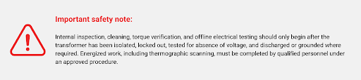
- De-energize and isolate the transformer, apply lockout/tagout, and verify absence of voltage.
- Discharge or ground components where required.
- Confirm that test equipment is suitable for the voltage class and within calibration.
Check the nameplate against the connected system and recorded tap position. Our transformer nameplate guide explains the ratings and connection information that should be confirmed before testing.
Thermographic scanning is different because the transformer must normally be energized and carrying a representative load. Complete it separately under the facility’s energized-work requirements.
-
Inspect for Contamination, Movement and Connection Heating
A visual inspection often reveals the mechanism behind a developing problem. Dust on windings and inside cooling ducts acts as a thermal barrier and can absorb moisture. Oxidized or loose joints increase contact resistance, producing localized heating.
Inspect:
- Coils, core surfaces, bus bars, supports, and enclosure surfaces for dust, residue, moisture, corrosion, or foreign material.
- Insulation for cracking, erosion, carbon tracking, discolouration, or other surface damage.
- Terminals and bus connections for oxidation, movement, looseness, or heat damage.
- Clamps, mounting bolts, winding supports, vibration isolators, barriers, guards, doors, and panels.
- Cable entries, gaskets, louvres, labels, and evidence of pests, condensation, or water entry.
- Any new or increasing noise, vibration, odour, or visible deformation.
A change in sound does not prove an internal winding fault. Loose panels, mounting resonance, core hardware, harmonic loading, and overexcitation can produce similar symptoms. Compare the condition with previous observations and operating load. Rex’s guide to transformer hum explains these mechanisms.
Do not apply a generic torque value to every connection. Use the transformer or connector manufacturer’s specified value and work only while the equipment is safely de-energized.
Cleaning methods must match the construction. A suitable industrial vacuum or manufacturer-approved dry, low-pressure air may be appropriate. High-pressure air can drive contamination deeper into windings, while solvents or wet cleaning methods may damage insulation or leave residue.
-
Use Electrical Tests to Confirm What Cannot Be Seen
Electrical testing is most useful when compared with commissioning values and previous records. Our power transformer testing guide provides additional context.
Insulation resistance. Measure phase-to-phase, phase-to-ground, and primary-to-secondary resistance where applicable, using the recommended test voltage. Sensitive controls, sensors, and surge-protection components may need isolation. A single reading is not a universal pass-or-fail result because temperature, humidity, test duration, transformer size, and insulation construction affect the value.
Transformer turns ratio. A ratio test can identify an incorrect tap setting, open circuit, shorted turns, winding damage, or unexpected phase difference. Compare the result with the nameplate ratio, actual tap position, applicable tolerance, and previous data. Explore Rex’s explanation of transformer turns ratio.
Winding resistance. Resistance testing can reveal deteriorated joints, tap-connection problems, damaged conductors, and phase imbalance. Correct readings for winding temperature before comparing phases or historical results.
Thermographic scanning. Scan terminals, bus and cable connections, enclosure surfaces, cooling paths, fan assemblies, and protective-device connections under a known load. Evaluate a hot connection with load balance, ambient temperature, connection geometry, and previous images.
Grounding, bonding and protection. Confirm that grounding and bonding conductors are present, clean, secure, and consistent with the system design. Document fuse, breaker, relay, alarm, and thermal-device settings. Repeated operation should be investigated rather than addressed by installing a larger device. For more details, see Rex’s guides to transformer grounding and bonding and transformer fuse sizing.
-
Verify the Entire Cooling Path
Restricted airflow is a common avoidable cause of elevated temperature, but the restriction may be outside the transformer. Clean internal ducts cannot compensate for a room that traps hot air or recirculates transformer exhaust toward the intake.
Inspect enclosure openings, cooling ducts, filters, fan guards, auxiliary fans, thermostats, controllers, alarms, and clearance around the enclosure. Remove stored material that obstructs airflow. Confirm that room intake and exhaust ventilation still match the heat released into the space.
Rex’s guides to dry-type transformer cooling and transformer clearance requirements explain why both internal and external airflow matter.
For fan-cooled units, verify that each fan starts at the intended temperature, rotates correctly, operates without excessive vibration, and moves air through the intended path. Confirm staged cooling and alarm functions.
-
Compare Load and Temperature Together
Temperature has meaning only when load and ambient conditions are known. Record phase currents, voltages where applicable, load percentage, ambient temperature, winding or sensor temperature, fan status, time, and the major process loads operating during the measurement.
Compare the results with the nameplate kVA, cooling configuration, temperature-rise rating, insulation class, expected load profile, and previous records. Rex’s guide to transformer insulation classes explains the distinction between insulation capability and specified temperature rise.
Investigate persistent overload, phase imbalance, recurring peak demand, fan or ventilation problems, and a gradual temperature increase under similar load. Harmonic-rich current can raise winding and stray losses even when root mean square current remains within the nameplate rating. A K-factor-rated transformer may be appropriate for some nonlinear loads, but the load spectrum and system requirements still need evaluation.
Critical transformers benefit from permanent temperature sensors, power meters, thermal relays, and remote alarms. Trends reveal seasonal changes, repeated overloads, and slow deterioration that a single annual reading can miss.
-
Treat the Environment as Part of the Application
A transformer selected for a clean electrical room may not remain suitable after the area changes. New processes can introduce conductive dust, chemicals, humidity, salt, or higher ambient temperature. Roof work, plumbing changes, and ventilation modifications can also create new exposure.
Inspect for dust, condensation, water entry, corrosive vapours, damaged coatings, failed gaskets, unsealed cable entries, damaged louvres, restricted working clearance, and room-ventilation changes.
A harsher environment may require improved filtration, a different enclosure, shorter maintenance intervals, or an encapsulated transformer. Marine and coastal applications require particular attention to salt, moisture, corrosion, and enclosure selection.
Documentation Turns Maintenance into Condition History
For each inspection, record the transformer identification and location, date, technician, operating conditions, load and temperature readings, visual findings, cleaning completed, torque checks, electrical test results, thermal images, photographs, components replaced, corrective actions, responsible person, target completion date, and next inspection date.
Compare each record with commissioning data and earlier results. A slowly declining insulation-resistance trend, a terminal becoming progressively hotter at comparable load, or recurring contamination in the same duct may be more significant than one isolated reading.
Consistent records also help separate transformer deterioration from external causes such as overloading, poor ventilation, harmonics, repeated transients, or environmental contamination.
When the Transformer Requires Qualified Evaluation
Routine external observation and housekeeping may be completed by qualified facility personnel. Specialized testing, internal investigation, and interpretation of abnormal results should be handled by experienced transformer technicians or the manufacturer.
Remove the unit from service and follow the facility’s emergency procedure when it is safe to do so if there is smoke, arcing, severe overheating, a burning odour, or visible deformation. Prompt evaluation is also required for:
- New or rapidly increasing noise or vibration.
- Cracked, tracked, eroded, or severely discoloured insulation.
- Evidence of partial discharge, moisture damage, or conductive contamination.
- Repeated temperatures above the expected operating range.
- Declining insulation resistance, abnormal ratio results, or significant winding-resistance imbalance.
- Repeated fuse, breaker, relay, fan-alarm, or thermal-sensor operation.
- Movement of windings, supports, terminals, or buswork.
Rex’s articles on partial discharge and transformer failure mechanisms explain why these symptoms should be investigated before repeated energization.
Conclusion
Dry-type transformer maintenance is not simply a cleaning schedule. It is a condition-assessment process that compares load, temperature, airflow, insulation condition, connection integrity, environmental exposure, and historical test data.
The practical trade-off is between inspection effort and operating risk. A lightly loaded transformer in a clean room may justify a longer interval, while a critical unit in a dusty, humid, harmonic-rich, or high-temperature application may require continuous monitoring and more frequent planned outages. The correct program detects changes before they reduce dielectric, thermal, or mechanical margin.
Rex Power Magnetics designs and manufactures dry-type transformers for commercial, industrial, infrastructure, marine, and specialized applications. When maintenance findings point to recurring overheating, environmental exposure, or a replacement requirement, the operating history should be reviewed together with the new transformer specification.
K-Factor Transformers Explained: Harmonic Heating, Ratings and Selection
Updated: August 17th, 2026
A K-rating is often selected from the connected equipment list: office loads receive one rating, data centres another, and variable-frequency drives another. That approach is convenient, but it can miss the actual transformer problem. Two facilities with similar equipment can produce very different harmonic spectra because of drive topology, loading, system impedance, uninterruptible power supply operating mode and the mix of single-phase loads.
The transformer does not respond to the equipment label. It responds to the current waveform. Correct selection therefore begins with the harmonic current spectrum, the transformer’s loss distribution and the neutral-current path. This article explains how harmonic currents create additional transformer heating, what a K-rating represents and when a K-rated transformer is not the complete solution.
How Harmonic Currents Create Transformer Heating
A linear load draws current approximately in proportion to the applied voltage. A non-linear load draws current in pulses. Switch-mode power supplies, uninterruptible power supplies, rectifiers, electronic lighting and variable-frequency drives all use power electronics that reshape the current waveform.
A distorted waveform can be resolved into the 60-hertz fundamental and harmonic components at integer multiples of that frequency. The 3rd harmonic is 180 hertz, the 5th is 300 hertz, and the 7th is 420 hertz. Six-pulse drives commonly produce strong 5th- and 7th-order currents, while single-phase electronic loads can produce significant triplen harmonics.
The additional heating is not explained by kilovolt-amperes alone. Harmonic current increases total root mean square current and therefore increases conductor I²R loss. Higher-frequency components also increase skin effect, proximity effect and winding eddy-current loss. Eddy-current heating rises more rapidly with harmonic order than the harmonic current magnitude by itself suggests, which can create local hot spots even when the transformer is not above nameplate kVA.
This is why a conventional transformer can run hotter on a non-linear load than on a sinusoidal load with the same measured root mean square current. The practical consequences are higher temperature rise, reduced efficiency and faster thermal ageing of the insulation system.
Harmonic forces may also add higher-frequency sound and vibration. A change in transformer noise should not automatically be attributed to harmonics, however. Loose hardware, excessive voltage, unusual loading and installation conditions must also be checked.
Why Triplen Harmonics Create a Separate Neutral Problem
In a balanced three-phase, four-wire system, the 60-hertz phase currents cancel in the neutral. Triplen harmonics, the 3rd, 9th, 15th and other odd multiples of three, are zero-sequence components. They are in phase on all three phases and add in the neutral instead of cancelling.
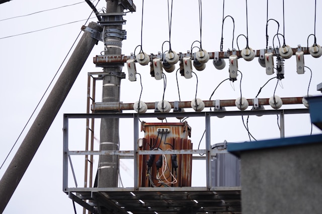
A transformer supplying a large concentration of line-to-neutral electronic loads can therefore have a neutral current approaching or exceeding the phase current. The heating is not limited to the windings. It can appear in the transformer neutral bus, cable, panelboard, busway and terminations.
K-factor transformer constructions address this condition with increased neutral capacity. Underwriters Laboratories (UL) 1561 K-factor designs are commonly provided with a neutral bar rated at approximately 200% of full-load current. That larger transformer neutral does not automatically make the downstream distribution system suitable. The neutral conductor and every connection in the return path still need to be checked for the expected triplen current.
The K-factor is a thermal index based on the harmonic current spectrum. Each harmonic component is weighted by the square of its order:
K = Σ [Iₕ(pu)² × h²]
Where:
- Iₕ(pu) is the root mean square current at harmonic order h, expressed per unit of rated root mean square load current.
- h is the harmonic order.
- Σ means that the weighted values for the harmonic spectrum are added together.
The h² term is the important part. A relatively small 13th-harmonic current can contribute materially to the calculated K-factor because it is weighted by 13².
For the same reason, total harmonic distortion alone is not enough to select a transformer. Two loads can have similar current total harmonic distortion but different K-factors if one spectrum contains more high-order current.
K-1 represents the baseline associated with little harmonic heating. Commonly specified ratings include K-4, K-9, K-13 and K-20, with higher ratings available for engineered applications.
A higher number does not mean better power quality, and it does not mean the transformer removes harmonics. It means the transformer is designed to carry a defined non-sinusoidal current spectrum without exceeding its specified temperature-rise limit.
Overspecifying the K-rating is not always harmless. Higher ratings can change winding geometry, impedance, sound level, physical size, cost and available fault current. The rating should match the expected spectrum rather than serve as a substitute for a power-quality study. NEMA’s guidance for data-centre transformer applications similarly treats the K-rating as one part of a wider design decision.
How a K-Rated Transformer Is Designed Differently
A K-rated dry-type transformer uses several design features to manage the additional losses created by non-sinusoidal load current.
Winding Conductor Design
The winding can use smaller parallel conductors, foil or other optimized conductor geometry to reduce eddy-current concentration. Additional conductor area may also be used to control root mean square heating.
The appropriate construction depends on current density, harmonic order, winding location and stray-flux exposure. Simply increasing conductor size without considering conductor geometry may not control high-frequency losses effectively.
Winding Arrangement and Cooling
Sectioning, spacing and cooling ducts can be arranged to move heat away from areas where harmonic losses concentrate.
The objective is not simply to lower average winding temperature. The design must prevent localized hot spots from exceeding the insulation system’s thermal capability. A transformer can have an acceptable average temperature while individual winding regions operate substantially hotter.
Core and Magnetic Design
The applied voltage and frequency still establish the main core flux. Harmonic load current primarily increases winding and stray losses rather than fundamental core flux.
Manufacturers may nevertheless use controlled flux density and low-loss core steel as part of the complete thermal design, particularly where stray flux and higher-frequency loss are significant. The exact balance between core size, winding arrangement, impedance and cooling depends on the transformer rating and the manufacturer’s construction method.
Neutral Construction
A 200% neutral is a defining practical feature for many low-voltage K-rated designs serving three-phase, four-wire systems. It addresses additive triplen current at the transformer.
It does not replace the need to specify downstream neutrals, panelboards and distribution equipment correctly.
These design measures are evaluated as a system. A Class H insulation system, larger conductor or extra ventilation by itself does not establish a K-rating. The transformer must meet the applicable construction, marking and temperature-rise requirements for its stated rating.
K-Rated and Harmonic-Mitigating Transformers Solve Different Problems
A K-factor -rated transformer is designed to withstand harmonic heating. The harmonic currents remain in the system.
A harmonic-mitigating transformer uses winding configuration, phase displacement and zero-sequence impedance to reduce selected harmonic currents or prevent them from propagating upstream. Line reactors, multi-pulse arrangements and active or passive filters may also be appropriate, depending on the load and the required point of compliance.
The selection depends on the engineering objective. Where the concern is transformer temperature rise, a correctly selected K-rated unit may be sufficient.
Where the concern is neutral current, voltage distortion, generator compatibility or harmonic current at the point of common coupling, harmonic mitigation must be evaluated at the system level. More background is available in Rex Power Magnetics’ guide to harmonics in power systems.
Selecting the Correct K-Rating
Selection should begin with an inventory of the loads and how they operate. Drive pulse configuration, uninterruptible power supply topology, server utilization, electronic lighting, battery chargers and the proportion of line-to-neutral loads all affect the spectrum.
Future load additions also matter. A transformer that is suitable at commissioning may no longer be suitable after an information technology or process expansion.
Where the harmonic content is material, individual current harmonics should be measured with a power-quality analyzer over a representative operating period. A short reading during light load can miss the condition that controls transformer heating.
Measurements should include normal production, high electronic-load demand, uninterruptible power supply operation and any operating mode that changes the rectifier or drive loading.
The following ranges are useful only for preliminary screening:
Equipment type should not be used as the final selection method. A lightly loaded modern uninterruptible power supply with an active front end may produce a less severe spectrum than an older or more heavily loaded unit. Drives with different pulse configurations can also impose substantially different harmonic currents.
An existing standard transformer does not always have to be replaced immediately. IEEE C57.110 provides methods for evaluating the capability of liquid-filled and dry-type two-winding transformers supplying non-sinusoidal load current. In some applications, derating the existing transformer may be technically acceptable.
That decision must also address neutral capacity, operating temperature and the connected equipment. Reducing kVA loading does not correct an undersized neutral. IEEE C57.110 also does not cover rectifier transformers, so those applications require separate design guidance.
The final transformer specification must still address:
- Kilovolt-ampere rating
- Voltage ratio and taps
- Impedance
- Temperature rise
- Enclosure and environmental conditions
- Efficiency
- Sound requirements
- Ambient temperature and altitude
- Ventilation
- Available short-circuit current
- Expected future loading
A K-rating does not correct an undersized transformer or an unsuitable installation.
Standards and Certification to Confirm
The applicable edition and certification requirements should be stated in the project specification rather than assumed from the words “K-rated.” The principal references include:
- UL 1561, Dry-Type General Purpose and Power Transformers
- CSA C22.2 No. 47:13 (R2023), Air-Cooled Transformers (Dry Type)
- IEEE C57.110-2018, Recommended Practice for Establishing Liquid-Immersed and Dry-Type Power and Distribution Transformer Capability When Supplying Nonsinusoidal Load Currents
- NEMA ST 20-2021, Dry-Type Transformers for General Applications
UL 1561 remains active and was most recently reaffirmed in 2023. CSA C22.2 No. 47:13 is listed as active and reaffirmed in 2023. NEMA ST 20-2021 supersedes the 2014 edition previously used in many transformer specifications.
Certification markings, energy-efficiency requirements and electrical-code obligations vary with voltage class and installation jurisdiction. They should be confirmed with the manufacturer and the project’s qualified electrical engineer before release for manufacture.
Conclusion
K-factor selection is a transformer thermal-design decision, not an equipment-category shortcut. The connected load creates a harmonic spectrum; that spectrum increases root mean square, eddy-current and stray losses; those losses determine winding hot spots, neutral loading and allowable transformer capacity.
A K-rated transformer is appropriate when the objective is to carry those currents without exceeding its temperature-rise limit. It is not a harmonic filter, and its enlarged neutral does not protect the rest of the distribution system.
The correct specification brings together the measured or calculated spectrum, neutral-current path, transformer loss design, kilovolt-ampere rating, impedance, environment and future loading. Where the harmonic profile is uncertain or system-wide distortion is the real concern, the study should be completed before the K-rating is fixed.
Load Calculation of Transformer: A Complete Guide
Updated: August 17th, 2026
Transformer load calculation is often presented as a simple exercise: add the connected equipment, apply a percentage margin, and select the next standard kVA rating. That approach can produce a number, but it does not necessarily produce the right transformer.
A transformer has to carry the maximum coincident load without exceeding its thermal limits. It may also have to start motors without an unacceptable voltage dip, supply nonlinear loads without excessive additional heating, and operate in ambient and ventilation conditions that differ from the assumptions behind its nameplate rating. These requirements are related, but they are not captured by one universal multiplier.
A useful load calculation therefore moves through three stages. First, establish the connected load on a consistent kVA basis. Next, determine the credible maximum demand using the applicable electrical code, operating sequence, and available measurements. Finally, check the electrical, thermal, and environmental conditions that can change the transformer selection.
This guide focuses on that complete process. For a narrower explanation of the single-phase and three-phase equations, see Rex Power Magnetics’ guide to calculating kVA for transformer sizing.
 What a Transformer Load Calculation Must Establish
 What a Transformer Load Calculation Must Establish
The connected load is the sum of all equipment that could be supplied by the transformer. Maximum demand is the greatest coincident load expected during the relevant operating period. The selected transformer rating must support that demand under the specified service conditions, with any required provision for load growth and transient duty.
Those values are not automatically the same. A facility may have several machines that are physically connected but prevented by controls from operating together. A commercial building may have lighting, receptacle, heating, cooling, and charging loads whose peaks occur at different times. Conversely, a process line may operate nearly all of its connected equipment continuously, leaving little difference between connected load and maximum demand.
The calculation must reflect the actual system. Applying an assumed percentage to the total connected load without a code basis, operating sequence, or measured profile can undersize the transformer just as easily as it can prevent oversizing.
Why Transformer Load Is Calculated in kVA
Transformers are rated in kilovolt-amperes (kVA), not kilowatts (kW), because their windings must carry current regardless of how much of the apparent power becomes useful real power at the load. A 50 kW load operating at a power factor of 0.80 requires 62.5 kVA from the transformer. Treating that load as 50 kVA would understate winding current by 20%.
For a single-phase load:
kVA = (V × I) ÷ 1,000
For a balanced three-phase load:
kVA = (√3 × VLL × IL) ÷ 1,000
Where:
VLL = line-to-line voltage
IL = line current in amperes
Using line-to-neutral voltage in the three-phase equation understates the load by a factor of √3.
When real power and power factor are known:
kVA = kW ÷ power factor
For a motor rated in horsepower:
Motor input kVA = (HP × 0.746) ÷ (efficiency × power factor)
Horsepower represents mechanical output, so both efficiency and power factor are required to estimate electrical input. If reliable motor nameplate current or manufacturer input data is available, calculating kVA from voltage and current is normally preferable to assuming typical efficiency and power-factor values.
These equations convert known load data into a common unit. Rex’s transformer calculators can perform the kVA, kW-to-kVA, and horsepower-to-kVA conversions, but the calculator cannot determine which loads will operate together or whether the resulting load profile is suitable for a particular transformer.
Building the Load Schedule
A defensible transformer selection begins with a load schedule that records what is connected, how it operates, and which source data supports the calculation.

Identify Every Connected Load
The schedule should include lighting, receptacles, heating, ventilation and air-conditioning equipment, motors, drives, uninterruptible power supplies, battery chargers, process heaters, welding equipment, control power, and planned additions. For each item, record the supply voltage, phase, full-load current or input kW, power factor where applicable, efficiency where mechanical output is given, quantity, and duty cycle.
Input data matters. A 40 W lamp rating does not necessarily represent the complete input of its driver or ballast. A motor’s horsepower rating describes shaft output rather than transformer input. A variable-frequency drive should be evaluated from its electrical input and operating duty, not simply from the motor horsepower connected to its output. Manufacturer data should be used where available.
Existing installations provide another source of evidence. Interval metering, power-quality monitoring, and supervisory control and data acquisition records can show the actual peak kVA, phase balance, power factor, harmonic current, and duration of loading. A short spot measurement may miss seasonal or production peaks, so the monitoring period has to represent the operating cycle being evaluated.
Convert the Loads to a Common kVA Basis
Each load should be converted to input kVA before it is added to the schedule. Resistive heaters may operate close to unity power factor, but electronic lighting, drives, rectifiers, and uninterruptible power supplies may not. “Capacitive load” does not require a different apparent-power formula; voltage and RMS current still determine VA. What changes is the current phase relationship and, for nonlinear equipment, the waveform.
Three-phase totals should also be checked by phase. A transformer may be within its total three-phase kVA rating while one phase or the neutral is overloaded by unevenly distributed single-phase loads. The load schedule should therefore show phase allocation rather than only one combined total.
Establish Maximum Coincident Demand
Connected load should be reduced only where the applicable electrical code or a defensible operating basis permits it. In Canada, the adopted edition of the Canadian Electrical Code, Part I and provincial or territorial amendments govern the installation. Project requirements may differ by jurisdiction, occupancy, load type, and authority having jurisdiction.
Demand factor and diversity factor should not be used interchangeably:
Demand factor = maximum demand ÷ total connected load
Demand factor is normally no greater than 1 because maximum demand does not exceed the connected load to which it is being compared.
Diversity factor = sum of individual maximum demands ÷ maximum coincident demand
Diversity factor is generally 1 or greater because individual load peaks may occur at different times. Coincidence factor, the reciprocal concept, is normally no greater than 1.
This terminology matters. Multiplying the connected load by an unsupported “diversity factor” of 0.7 may appear conservative, but it is actually applying a coincidence or demand assumption. The assumption needs a code rule, interlocked operating sequence, historical profile, or other documented basis.
Account for Duty Cycle and Load Duration
Two loads with the same peak kVA can impose different thermal duties. A process that remains near maximum demand for every production shift heats the transformer differently from an intermittent machine that runs for a few minutes each hour. Cyclic loading may permit thermal behaviour that a simple steady-state total does not describe, but any loading above the nameplate rating requires an application-specific thermal assessment rather than an assumed overload allowance.
The transformer nameplate rating represents continuous capability under defined conditions. Rex’s transformer rating guide explains how rated kVA is connected to voltage, current, temperature rise, insulation system, cooling, and service environment.
Check Motor Starting and Other Transient Loads
Motor running kVA establishes the steady-state contribution. Motor starting is a separate check. Across-the-line starting can draw several times the running current, and the resulting current through the source, transformer, and conductor impedance produces a temporary voltage drop.
The correct assessment uses the motor’s locked-rotor current or code information, starting method, acceleration time, number of motors already running, transformer impedance, upstream source strength, and allowable voltage dip at the motor and other connected equipment. The full starting kVA is not normally added to the continuous load as though it were permanent. Instead, it is evaluated as a transient duty and voltage-performance problem.
Transformer energization inrush is different again. It is created by core flux during energization and affects protection coordination and source disturbance, but it is not part of the downstream operating-load total. Rex’s guide to transformer inrush current explains why switching angle, residual flux, core design, and source impedance influence this event.
Evaluate Nonlinear Loads Separately
Variable-frequency drives, uninterruptible power supplies, rectifiers, LED drivers, computers, and other power-electronic loads draw nonsinusoidal current. Their true RMS current contributes to winding heating, while harmonic components increase eddy-current and other stray losses. Triplen harmonics from single-phase nonlinear loads can also add in the neutral of a three-phase four-wire system.
A correct fundamental-frequency kVA calculation can therefore still select the wrong transformer construction. The harmonic spectrum, current total harmonic distortion, neutral loading, and load mix may require a K-factor-rated or harmonic-mitigating design rather than simply a larger general-purpose unit. IEEE C57.110-2018 provides methods for evaluating transformer capability when supplying nonsinusoidal load currents. Rex’s guide to K-factor transformers and harmonics explains how harmonic load characteristics affect selection.
Check Ambient, Altitude, Enclosure, and Cooling
The calculated kVA assumes the transformer can reject the heat produced by its core, winding, and stray losses. Elevated ambient temperature reduces the temperature margin between the windings and their allowable limit. High altitude reduces air density and cooling effectiveness. Restricted clearances, blocked ventilation openings, dust accumulation, solar loading, and an enclosure selected for a difficult environment can also change thermal performance.
These conditions should be given to the manufacturer rather than addressed through a generic percentage margin. Rex’s guide to thermal management in dry-type transformers explains how cooling method, insulation class, temperature rise, airflow, ambient conditions, and monitoring work together.
Add Future Capacity Deliberately
Future growth is a project requirement, not a universal 25% rule. A fixed process with a known production limit may need little spare capacity. A tenant building, phased industrial expansion, data centre, or electrification project may justify substantially more. The allowance should be tied to identified future loads, timing, available space, upstream capacity, and the cost of later replacement.
Excessive oversizing also has consequences. A larger transformer costs more, occupies more space, may increase available fault current, and carries no-load losses whenever it is energized. Since load losses rise approximately with the square of load current while no-load losses remain present regardless of output, the expected operating profile should be considered alongside initial kVA. Rex’s guide to transformer losses explains this relationship.
Worked Transformer Load Calculation
Consider a small three-phase facility supplied by one transformer. The connected load consists of fifty lighting fixtures with 40 W input each at 0.95 power factor and three 5 hp motors. Each motor operates at 85% efficiency and 0.80 power factor.
The lighting load is:
Lighting kVA = 2.0 kW ÷ 0.95 = 2.11 kVA
The running load of each motor is:
Motor kVA = (5 × 0.746) ÷ (0.85 × 0.80) = 5.49 kVA
The total connected running load is therefore:
Connected load = 2.11 + (3 × 5.49) = 18.58 kVA
Suppose the documented control sequence permits only two motors to run simultaneously, while the complete lighting load may be on. The calculated maximum steady-state operating load becomes:
Maximum operating load = 2.11 + (2 × 5.49) = 13.09 kVA
If the project also identifies 4 kVA of future coincident load, the design load becomes:
Design load = 13.09 + 4.00 = 17.09 kVA
On continuous kVA alone, a 25 kVA transformer becomes a reasonable candidate. It is not yet a complete selection. If one motor starts while the other two and the lighting remain in service, the transient current may produce an unacceptable voltage dip even though the normal operating load is well below 25 kVA. The motor-starting method, locked-rotor current, transformer impedance, source impedance, conductor voltage drop, acceleration time, and sensitivity of the other loads must still be checked.
The example demonstrates why the old shortcut of multiplying connected load by 0.7 and then by 1.25 is not a sound substitute for an operating analysis. The two arbitrary factors can partly cancel each other while hiding the information that actually determines whether the system will work.
What Transformer Calculator Tools Can and Cannot Do
A calculator is useful for converting volts and amperes to kVA, converting kW at a stated power factor, or estimating motor input from horsepower, efficiency, and power factor. It also reduces arithmetic and unit-conversion errors when several scenarios have to be checked.
It cannot know whether the source data represents input or output power, whether loads are balanced, which equipment operates simultaneously, whether a demand factor is permitted, or whether a short-duration load creates an unacceptable voltage dip. It also cannot infer the harmonic spectrum, ambient conditions, altitude, enclosure restrictions, available fault current, or future expansion plan unless those conditions are explicitly modelled.
Calculator output should therefore be treated as one part of the load schedule, not as approval of the final transformer. The calculated rating should be checked against the transformer’s voltage, phase, frequency, winding connection, taps, impedance, temperature rise, insulation class, enclosure, cooling method, and applicable standards. Rex’s transformer nameplate guide explains where the finished transformer’s principal ratings and connection information are recorded.
Common Transformer Load Calculation Errors
The most common error is mixing kW and kVA. Power factor must be applied when real power is converted to apparent power, but it should not be applied a second time when voltage and RMS current already define kVA.
Another error is adding output ratings rather than electrical input. Motor horsepower, delivered uninterruptible-power-supply output, lamp wattage, and drive output do not necessarily equal the kVA drawn from the transformer. Efficiency, power factor, auxiliaries, and operating point all matter.
Demand assumptions also cause significant errors. Loads should not be removed from the maximum-demand calculation simply because they “usually” do not run together. The operating restriction must be established through code-permitted demand factors, interlocks, process logic, or representative measurements.
Starting current is often handled incorrectly in one of two ways. Ignoring it can lead to failed motor acceleration, contactor dropout, dimming, or nuisance operation of protective devices. Adding it to continuous kVA as though it never decays can lead to unnecessary oversizing. It needs a transient check.
Finally, a correct kVA total can still be incomplete. Phase imbalance, nonlinear current, neutral loading, ambient temperature, altitude, restricted ventilation, voltage regulation, short-circuit duty, and protection coordination can all affect the equipment specification after the arithmetic is finished.
Information Required for Final Transformer Selection
Before a calculated load becomes a purchase specification, the primary and secondary voltage, phase, frequency, and winding connection should be confirmed. The connected load schedule and maximum coincident demand should also be reviewed, along with the continuous, intermittent, cyclic, and transient duties the transformer will serve.
Loads that create unusual electrical demands require additional attention. For motor loads, confirm the starting method, starting current, and permissible voltage dip. For nonlinear loads, assess the expected percentage of nonlinear loading, harmonic spectrum, and neutral current. Planned equipment additions should also be considered so the transformer includes an appropriate expansion allowance without being unnecessarily oversized.
The installation conditions are equally important. Confirm the ambient-temperature range, altitude, ventilation, and enclosure requirements, as these factors affect cooling and usable capacity. Required impedance, voltage regulation, and available fault-current limits must also be established so the transformer performs correctly within the wider electrical system.
Finally, review the protection, grounding, bonding, and applicable electrical-code requirements. The purchase specification should identify the relevant CSA, UL, IEEE, NEMA, efficiency, and project-specific standards by their exact document numbers and required editions.
NEMA’s dry-type transformer purchasing specification guide provides a useful reference for many of the electrical, environmental, construction, testing, and documentation details that have to be defined after the load is established.
Conclusion
Transformer load calculation is not simply connected kVA plus a safety percentage. The calculation has to distinguish connected load from maximum coincident demand, use correct electrical input data, and account for duty cycle, motor starting, nonlinear current, environmental conditions, and planned growth.
The arithmetic identifies a candidate kVA rating. The surrounding system determines whether that candidate will operate reliably. A transformer that is adequate thermally may still produce an unacceptable voltage dip during starting, while a transformer that carries the fundamental-frequency kVA may still overheat under harmonic current. Conversely, unnecessary spare capacity can increase capital cost and no-load losses without solving a defined application problem.
For new or complex installations, involve Rex Power Magnetics early in the selection process. Share the load schedule, operating sequence, source characteristics, harmonic profile, environmental conditions, and anticipated future growth. Our engineering team can use this information to select and design a transformer for the system’s actual operating duty, rather than relying on a generic capacity percentage that may not reflect the application.
Types of Transformers Explained – An Ultimate Guide
Transformers are essential components in electrical systems, allowing the efficient transmission and distribution of electrical energy. A transformer’s core function is to alter the voltage of electricity, either stepping it up or stepping it down, depending on the application. However, what are the primary transformer types? The answer is that transformers come in various types, each designed for specific tasks in power generation, transmission, and distribution.
Let’s uncover what are the main types of transformers and how they work.
Top Classification of Transformers by Function
1. Step-Up Transformer
A step-up transformer is designed to increase the voltage level of electricity. This is crucial for transmitting power over long distances, as higher voltage allows electricity to travel efficiently with minimal loss. These transformers are typically used in power generation stations to boost the voltage before it enters the transmission lines.
2. Step-Down Transformer
On the other hand, a step-down transformer decreases the voltage of electrical power to safer, usable levels. Once electricity reaches its destination, it must be reduced to levels that are safe for commercial, industrial, and residential use. Step-down transformers are commonly found in substations and at the end of power transmission lines.
3. Isolation Transformer
Galvanic isolation between its primary and secondary circuits is provided by an isolation transformer. This means there is no direct electrical connection between the two circuits, enhancing safety and protecting sensitive equipment. Medical equipment, lab environments, and locations needing precise electrical performance frequently use isolation transformers.
4. Power Transformers
Power transformers are used in large-scale electrical systems, playing a vital role in power generation, transmission, and distribution. These transformers operate under high voltage and are crucial for ensuring electricity reaches users effectively and safely.
5. Generator Transformers
Generator transformers are step-up transformers used in power stations to increase the voltage from the generator before it is transmitted over long distances. These transformers are specifically designed to handle the high output of power plants, ensuring the electricity is in the proper voltage range for transmission.
6. Transmission Transformers
Transmission transformers are designed to handle the high-voltage transfer of electricity over long distances. These transformers are used in substations to step down the voltage for distribution. They are designed to withstand high pressure and high electrical loads.
7. Distribution Transformers
Distribution transformers are used to deliver the final voltage to consumers. These transformers step down the high-voltage electricity from transmission lines to the lower, usable voltages found in homes and businesses. They are critical for ensuring electricity is safe and effective for everyday use.
Main Classification by Cooling Method
Transformers can also be classified based on their cooling method. For high-power transformers to remain efficient and avoid overheating, cooling is crucial.
1. Oil-Immersed Transformers
Oil-immersed transformers are cooled using oil, which acts as a heat dissipation medium. The oil absorbs the heat generated by the transformer’s core and windings, helping to prevent overheating. These transformers are commonly used in outdoor applications due to their ability to handle high power levels and provide efficient cooling.
2. Dry-Type Transformers
Dry-type transformers, on the other hand, are not immersed in oil and instead use air or other gases for cooling. These are often used in indoor settings or in locations where oil-immersed transformers might pose a risk. They are safer for sensitive environments and are commonly used in commercial buildings, hospitals, and high-traffic areas.

The Special Purpose Transformers
While the primary function of a transformer is to adjust voltage levels, there are special-purpose transformers designed for specific applications that go beyond the basic step-up or step-down functions.
1. Instrument Transformers
Instrument transformers, such as current transformers (CT) and potential transformers (PT), are used for metering and protection in electrical systems. They measure current and voltage levels and provide accurate readings for monitoring and control.
2. Autotransformers
Autotransformers have a single winding that acts as both the primary and secondary winding. These transformers are more compact and efficient than their two-winding counterparts, but they offer less electrical isolation. They are often used in applications where size and efficiency are crucial.
3. K-Factor Rated Transformers
K-factor-rated transformers are designed to handle non-linear loads that produce harmonic distortion. These transformers are commonly used in industrial applications with variable-speed drives or other equipment that may generate harmonic currents.
4. Harmonic Mitigating Transformers
Harmonic mitigating transformers are used to reduce the impact of harmonic distortion caused by non-linear loads. These transformers help improve power quality and extend the life of electrical equipment by mitigating harmonic currents that can cause overheating and inefficiencies.
5. General Purpose Isolation Transformers
General-purpose isolation transformers are used to provide isolation in a wide range of applications, including medical devices, laboratory equipment, and sensitive machinery, ensuring the protection of both equipment and users.
Key Takeaways
- Transformers are essential in electrical systems, adjusting voltage levels for power generation, transmission, and distribution.
- There are different types of transformers based on their function, including step-up, step-down, and isolation transformers.
- Power transformers are used in large-scale applications, such as power stations, transmission lines, and distribution networks.
- Transformers are generally classified by cooling methods (oil-immersed and dry-type).
- Special-purpose transformers, such as autotransformers and instrument transformers, serve unique applications in industrial and commercial sectors.
- Transformers are critical in integrating renewable energy sources, maintaining the efficiency of power grids, and ensuring the safety of electrical systems in residential, commercial, and industrial settings.
- Understanding the different types of transformers and their applications helps ensure that electrical systems operate efficiently, safely, and reliably, regardless of the industry or setting.
Power Transformer Design and Key Specifications
Transformers are essential parts of electrical systems because they make it easier for electrical energy to move between circuits with varying voltages. Whether you’re stepping up voltage for long-distance transmission or stepping it down for safe residential and industrial use, transformer design plays a crucial role in ensuring efficiency, safety, and reliability. In this article, we’ll explore the power transformer design, the critical factors involved in designing transformers, and the key transformer specifications that guide their optimal performance.
Understanding Power Transformer Design
The power transformer design is a meticulous process that involves careful consideration of electrical, mechanical, and thermal properties. The goal of designing a transformer is to create a device that can handle the required voltage levels, power ratings, and operational conditions. The specification of the transformer is based on the type of application, such as power generation, transmission, or distribution. Each transformer design is customized to meet specific requirements like efficiency, cooling methods, load capacity, and safety features.
Key Factors in Designing Transformers
When you design a transformer, several factors need to be considered to ensure that it performs optimally and safely:
Core Design: The core material and its shape play a significant role in the transformer’s efficiency. Silicon steel and other materials with high magnetic permeability are frequently utilized to reduce energy loss.
Windings: Electrical energy is transferred by means of the windings. The number of turns in the primary and secondary coils, as well as the wire’s material (typically copper or aluminum), are critical in determining the voltage and current levels of the transformer.
Cooling Method: Maintaining the transformer’s performance requires cooling. Depending on their size, use, and climate, transformers can be cooled with either oil (oil-immersed transformers) or air (dry-type transformers).
Insulation: Proper insulation ensures that the windings and other electrical components do not come into contact with each other, preventing short circuits and failures. High-quality insulation materials, such as paper, oil, and synthetic resins, are commonly used in transformer designs.
Safety and Protection Features: Transformers are designed to handle high voltage and current, so it is essential to incorporate protective elements such as bushings, tap changers, and relays to prevent damage and ensure safe operation.
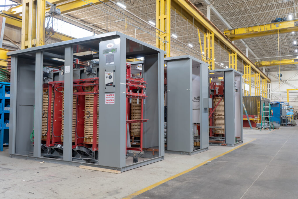
Key Transformer Specifications
The transformer specifications define the limits within which a transformer will operate safely and efficiently. Below are the essential specifications that need to be considered when designing a power transformer:
Voltage Rating: The voltage rating of the transformer defines the maximum voltage the transformer can handle. This includes both the primary and secondary voltage ratings, which determine the level of voltage transformation.
Power Rating: The power rating, which is typically expressed in megavolt-amperes (MVA) or kilovolt-amperes (kVA), shows the highest power that the transformer can manage without failing or overheating.
Impedance: The impedance of a transformer defines the resistance to the current flow. It is crucial for determining the voltage drop, load sharing, and short-circuit performance.
Frequency: Transformers are designed to operate at a specific frequency, typically 50 Hz or 60 Hz, depending on the region. The frequency affects the transformer’s core design and overall performance.
Temperature Rise: The permitted temperature increase while the transformer is operating is indicated by the temperature rise standard. It is a critical factor in ensuring the transformer’s longevity and safe operation.
Efficiency: Transformer efficiency is a key specification, representing the ratio of output power to input power. High efficiency is essential for minimizing energy loss and operating costs.
Tap Changing Mechanism: Transformers often come with tap changers that allow for voltage adjustment under varying load conditions. Designing transformers to incorporate automatic or manual tap changers is essential for maintaining stable voltage.
The power transformer design process involves a careful balance of electrical engineering principles, material selection, and safety features. By understanding the critical transformer specifications, such as voltage rating, impedance, and cooling methods, engineers can create efficient and reliable transformers that meet specific industrial and commercial needs. Whether you’re tasked with designing transformers for power plants, transmission grids, or distribution systems, these key design considerations and specifications ensure that the transformer performs optimally throughout its service life.
Incorporating the correct specification of the transformer is vital for achieving maximum efficiency, safety, and reliability in any electrical system.
How to Pick the Ideal Transformer for Your Power System
Choosing the right transformer isn’t just a routine task; it’s a pivotal decision, akin to picking the ideal location or investing in essential machinery. Consider it the heartbeat of your electrical system. A healthy, well-suited transformer keeps everything humming, prevents costly surprises, and lets you rest easy. A weak or inadequate one? Buckle up for headaches, unexpected shutdowns, and potential dangers.
A transformer that’s properly sized and built to last ensures your electrical systems run safely and efficiently. This translates to less downtime, longer equipment life, and savings on operating costs down the road. On the other hand, skimping with an undersized or cheap transformer can lead to overheating, unstable voltage, higher repair bills, and even safety risks. Think of it as trying to power your house with a generator meant for a campsite.
Whether you are outfitting a brand-new facility, scaling up current operations, or finally swapping out that ancient, sputtering transformer tucked away in the back, understand that your transformer choice impacts efficiency, performance, and safety for years to come. So, how do you choose a transformer? Let’s get started.
Transformer Capacity and Future Growth: Planning Ahead
Capacity should be the cornerstone of any transformer selection process. Misjudge this, and you’re setting yourself up for trouble. Capacity, measured in kilovolt-amperes (kVA), must satisfy your facility’s current electrical needs and have some wiggle room for when you grow. Think of it like packing for a trip; you always bring a little extra space, right?
Start by carefully evaluating your current load profile, the sum total of electricity your facility demands from the grid when things are busiest. Consider everything: lighting, HVAC, that energy-guzzling CNC machine, and even the coffee machine in the breakroom. Reviewing this is similar to getting new glasses; you want to be able to see everything!
Choosing a transformer that typically operates at around 80% of its rated capacity is a smart move. This gives you a safety net, helps prevent overheating, eases stress on the components, and prolongs its lifespan. Driving the transformer at full capacity is like flooring your car all the time; you wear it down. Overloading it has some considerable impact: premature breakdown, emergency replacements, and halted production lines, which hurt deadlines, revenue, and reputations. A transformer operating over 90% will likely fail in 5 years.
Got expansion on your radar? Definitely plan for extra headroom. Paying a bit extra now beats replacing the transformer later. A transformer sized just for today could need replacing fast when you add equipment. Upping the capacity on the front end can save money compared to buying a second transformer down the road or dealing with constant overloads. What’s on the horizon, a new production line? More hefty equipment? Bake it all in. Another thing to consider is doing a phased expansion. Start with the smaller capacity now, and add transformers after the expansion.
Voltage Considerations: Primary and Secondary – Match Game
Precise voltage matching is essential for both safety and efficiency. Mismatched voltages can fry equipment quicker than you can say “insurance claim.” You need to nail down the primary voltage (from the utility) and the secondary voltage (what your equipment needs).
Here in Canada, we frequently see primary voltages like 4.16kV, 13.8kV, and 25kV. But don’t assume. Contact your utility and confirm your exact voltage. Keep this information close like a password, and double-check its accuracy. Secondary voltages often land between 208V and 600V, based on what kind of equipment you’re running. Modern industrial plants sometimes use cascaded systems. Cascading allows more granular voltage delivery to different zones.
Also, double-check the system frequency (50Hz vs. 60Hz). North America tends to use 60Hz, while other regions prefer 50Hz. An incorrect frequency can cause equipment damage, and of course, void those warranties. Imagine trying to fit a square peg in a round hole; it’s just not going to work. If the frequency parameter doesn’t match, it can affect core losses and impedance of the unit, and it will age faster.
Transformer Type and Construction: Finding the Right Transformer
Different transformers are suitable for different jobs. Using the wrong tool never works well. So here is a rundown of the main options:
Single-Phase Transformers – Great for light commercial or residential applications where you don’t need three-phase power. Consider small shops or local offices. These are smaller, less expensive, and simpler to install and maintain.
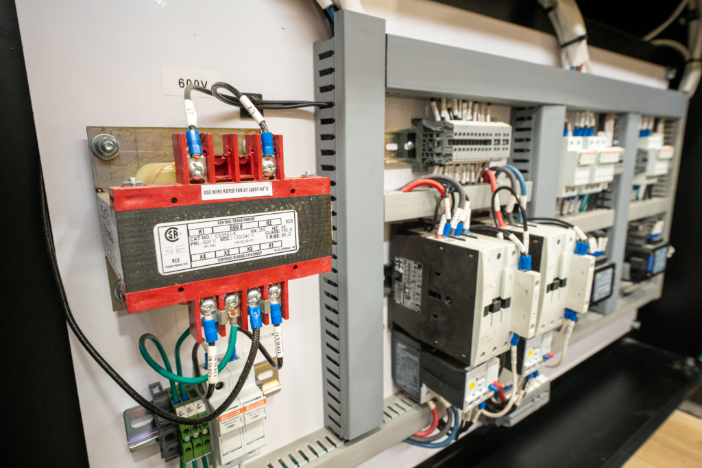
Three-Phase Transformers – Best for industrial and commercial facilities with major three-phase electrical loads, offer higher efficiency and a better price per kVA. This is the unit that does all the heavy lifting for larger operations. This class of transformer handles a much higher demand load than the single-phase version.
Dry-Type Transformers – These use air for cooling. For the most part, these are safer for indoor use, require less upkeep, and make less noise. Picture this as the “cleaner” choice. Additionally, these units utilize high-temperature insulation systems. And overall, dry-type units can withstand higher operating conditions and reduced fire hazards.
Oil-Filled Transformers – Top-notch cooling and higher efficiency make these perfect for outdoor or heavy-duty uses. However, you will need containment measures for leaks, and they require a bit of upkeep. These are known as “heavy lifters,” since the oil effectively distributes heat, enabling large loads.
Choosing between dry-type and oil-filled comes down to cooling demands and maintenance requirements. Are you worried about upkeep or maximizing efficiency? Also, check out cast resin units. They reduce the risk of environmental damage and fires!
Calculating kVA Requirements: Crunching the Numbers
Figuring out the right kVA is critical (we mentioned it twice, to make sure it sticks). The formula changes when going from single-phase to three-phase setups:
Single-Phase kVA Formula:
𝑘VA = (V × I) / 1000
Where, V = Volts, I = Current in Amps
Three-Phase kVA Formula:
𝑘VA = (V × I × 1.732) / 1000
V = Volts and I = Current. (1.732 is the square root of 3).
Here’s an example. For example, let’s say a three-phase load has a current draw of 100A and the voltage is at 480V. Calculation:
kVA = (480 × 100 × 1.732) / 1000 ≈ 83 kVA
Always go beyond the next standard kVA to ensure you’ve got ample capacity. In this case, you’d likely select 100 kVA. If you have to choose between too little and too much, pick more. A power quality audit, analyzing and recording actual loads, ensures you are getting correct values.
Environmental and Load Conditions: Understanding the Context It is In
When selecting a transformer, considering environmental factors is important. Think of picking clothing for the day. You wouldn’t pick a light jacket for winter.
Ambient Temperature: Transformers are typically rated at 30°C. If your facility runs hotter than that, you may have to go with a larger transformer or use an air-cooling setup. A 10°C bump above that cuts the unit’s life in half!.
Installation Location: Outdoor units must have enclosures to protect them from the elements. Indoor setups need to minimize noise, mainly when offices sit in proximity. Check noise levels and ensure they don’t bother workers.
Load Type: Lighting, manufacturing equipment, and variable frequency drives (VFDs) all require transformers that do different things. If harmonic distortions are high, use a K-rated transformer to prevent excess heat. Linear loads have a more stable, sinusoidal draw, while non-linear loads cause harmonic issues, causing overheating and decreasing efficiency.
Specialized transformers exist for harsh environments. In essence, there’s a transformer to fix any challenge. These units require robust sealing and advanced coatings.
Transformer Quality and Reliability Details: Maximizing Longevity
Not all transformers provide the performance. Saving on the transformer leads to more issues down the road. Like using cheap tires on a car, they wear fast and aren’t reliable. Things to look for:
Core Material: Steel laminations reduce loss and improve how well the unit works. Better core material leads to cooler operation, as well as better reliability. In addition, amorphous steel core units take further gains in unit efficiency.
Conductor Material: Copper windings provide superior conductivity and efficiency over aluminum. By using copper, less heat is generated for a longer life. Aluminum, while more affordable, increases loss value.
Insulation Class: Enhanced insulation extends a transformer’s operating life. Insulation classes are rated as A, B, F, and H, with H offering better aging characteristics.
Testing: Verify stringent tests for efficiency, withstanding impulse, and resistance. Any manufacturer stands by these values with comprehensive testing data. These measurements adhere to IEEE/IEC measurements.
Yes, spending more money gets quality. It pays for itself due to reducing energy cost, minimizing maintenance, and preventing unplanned outages, equating to a lower total cost of ownership. Thermographic surveys ensure that you can detect failures ahead of time.
Lead Times and Availability: Being on Time
Lead times can significantly affect when projects are completed. Not having a transformer creates a huge issue in business operations! Because of some recent worldwide issues with getting products and supplies, it’s important to manage lead times for project completion.
Custom units may take months. Fortunately, some suppliers carry a supply of the units and can ship quickly to minimize downtime. If a unit fails, a business needs to have a plan on deck to handle a failure. Keeping an on-site unit minimizes that risk.
Customization and Retrofits: Maximizing Compatibility
When a transformer breaks, it’s uncommon to have it line up for the existing installation. So, flexibility is needed. Units with tap settings and changeable mounting configurations allow you to adapt.
Custom work can help retrofit a unit to install easily. As a result, install times decrease, and costly rework can be avoided. Working with engineering partners assists with tricky installs. Also, verify customization during supplier evaluation. Modular designs lower integration expenses.
Sourcing and Vendor Support: Selecting The Right Partner
A supplier focuses on assisting you through the entire process. Select a competent and experienced team. Having a track record leads to long-term service availability.
Find vendors that:
Experience: Experienced people solve problems. Ask for references from other clients to make sure that they are competent at what they do.
Customer service: Customer service can resolve any issue and find suppliers that are easy to deal with. Ensure 24/7 support with communication channels.
Tech Support: Helps with installation and troubleshooting, and they may be certified engineers.
Working with a supplier ensures you have the right transformer along with timely project completion. Consider monitoring, maintenance, and overall optimization of performance.
Summary Checklist
Here are key steps in selecting transformers:
- Determine future and current loading.
- Look at voltages and frequencies carefully.
- Select the right type for the environment.
- Verify tests and quality.
- Understand realistic lead/availability.
- Decide that custom-fitting is a priority.
- Partner with a strong vendor.
Selecting transforms is about determining how to meet demands and finding how to sustain business goals. By investing safely, businesses can have enhanced quality. Make sure the plan ensures proactive maintenance is optimized.
Transformer Lifespan: How Design, Load, and Environment Affect Service Life
Updated: August 17th, 2026
A transformer does not reach the end of its useful life simply because it passes a particular number of years in service. Some units operate reliably for decades, while others develop insulation or thermal problems much earlier. The difference is usually found in the relationship between design, temperature, load duty, environment, and maintenance.
For dry-type transformers, the insulation system is central to service life. Heat gradually changes the electrical and mechanical properties of insulation, but average load alone does not reveal the complete thermal duty. Harmonic current, blocked airflow, high ambient temperature, phase imbalance, repeated overloads, and poor connections can create hot spots even when the apparent load seems acceptable.
Transformer lifespan is therefore an asset-condition question, not a fixed calendar estimate. Understanding what has stressed the transformer, and for how long, gives teams a stronger basis for selection, maintenance, and replacement planning.
Transformer Age is Not the Same as Transformer Condition
Published life ranges can be useful for high-level asset planning, but they should not be treated as an expiry date. Chronological age records the time since manufacture or energization. Condition reflects what has happened to the transformer during that time.
A lightly loaded transformer in a clean, well-ventilated electrical room may retain substantial service capability after many years. A newer unit can age more rapidly if it operates near a heat source, repeatedly carries harmonic-rich current, experiences moisture or contamination, or has ventilation openings obstructed by dust or stored material.
The important concept is consumed insulation life. IEC 60076-12, the loading guide for dry-type power transformers, provides a method for estimating ageing rate and life consumption as functions of operating temperature, time, and loading. This does not produce an exact failure date. It provides a thermal model that becomes more useful when it is supported by reliable load and temperature history.
A credible remaining-life assessment combines operating history with inspection, testing, and knowledge of the application. It also considers terminations, supports, cooling equipment, controls, and contamination rather than insulation alone.
Why Temperature Drives Insulation Ageing
A transformer’s kVA rating is fundamentally a thermal limit. Core losses are present whenever the transformer is energized, while winding and stray losses increase with load current. The resulting heat must move from the conductor through the insulation and winding structure to the surrounding air.
The most highly stressed location is the winding hot spot, not necessarily the point measured by an enclosure sensor or an infrared scan. Rex’s transformer rating guide explains how rated kVA, current, temperature rise, insulation class, cooling, and service conditions work together.
Insulation class and temperature rise must also be distinguished. The insulation class identifies the thermal capability of the insulation system. The specified winding temperature rise describes how much the average winding temperature may increase above the reference ambient under rated conditions. A higher insulation class does not make every operating temperature equally desirable, and temperature margin is not a general-purpose overload allowance.
Winding geometry, conductor arrangement, cooling ducts, losses, and enclosure ventilation all influence hot-spot temperature. Good design limits localized heating instead of relying only on an acceptable average. Rex’s article on thermal management in dry-type transformers examines how airflow and insulation design control this process.
Design Determines How Stress Is Managed
Long service life begins with a transformer designed for the actual duty. Copper and aluminum windings can both provide reliable service when conductor area, joints, bracing, insulation, and cooling are engineered correctly. Conductor material alone does not determine longevity.
Winding construction affects both heat transfer and short-circuit strength. Conductor dimensions, layer or disc arrangement, insulation thickness, cooling channels, clamping, and bracing influence how the winding responds to continuous load, starting current, and fault forces. Rex’s guide to transformer winding design explains why electrical, thermal, and mechanical requirements cannot be separated.
Core design also matters. Flux density and core-joint construction affect excitation current, no-load loss, temperature, and sound. Operation at excessive volts per hertz can push the core closer to saturation, increasing magnetizing current and heating. This may occur because of overvoltage, underfrequency, incorrect taps, or an application that does not match the nameplate frequency.
Enclosure and cooling design must suit the installation. A ventilated transformer relies on clean air passages and adequate clearance. Encapsulated or cast-coil construction may better resist particular contaminants or moisture conditions, but no construction solves every environmental problem.
Load Profile Matters More Than One Current Reading
Continuous overload increases winding temperature, but duty cannot be judged from one spot measurement. Load duration, cycles, starting events, phase balance, ambient temperature, and cooling equipment all affect the result.
Repeated heating and cooling can also impose mechanical stress. Conductors, insulation, terminals, and supports expand and contract at different rates. A transformer designed for cyclic duty can manage these changes, but severe or frequent temperature swings can contribute to loosened connections and insulation deterioration over time.
Motor starting, transformer energization, welding loads, and other short-duration events require separate consideration. They may not add much to average thermal load, but they can cause voltage drop and electromechanical force. A fault is more severe: short-circuit current produces forces that rise approximately with the square of current. Even when protective devices clear the event, winding bracing and connections may have been stressed.
Proper transformer sizing and selection require more than rounding a load calculation to the next standard kVA. The design must reflect coincident demand, duty cycle, inrush, motor starting, growth, source conditions, and the cooling environment.
Harmonic Loads Can Consume Thermal Margin
Variable-frequency drives, uninterruptible power supplies, rectifiers, LED drivers, computers, battery chargers, and other power-electronic loads draw nonsinusoidal current. A transformer can be within its nameplate kVA and still experience greater-than-expected heating if the design does not account for the harmonic spectrum.
Harmonic current increases winding eddy-current and other stray losses. Triplen harmonics from single-phase nonlinear loads can add in a three-phase four-wire neutral, while phase imbalance can place greater thermal duty on one winding.
IEEE C57.110-2018 provides methods for evaluating transformer capability when supplying nonsinusoidal load currents and information for specifying new transformers for such loads. Depending on the measured or predicted spectrum, the correct response may be a K-factor-rated transformer, a harmonic-mitigating transformer, revised winding construction, or another system-level measure. A K-factor rating indicates an ability to withstand defined harmonic heating; it does not filter harmonics. Rex’s guide to K-factor transformers and harmonics explains this distinction.
Environment Can Change the Available Thermal Capacity

Nameplate capability is based on defined service conditions. When the actual installation departs from those conditions, the transformer may have less thermal margin than the load calculation suggests.
High ambient temperature reduces the margin available for heat rejection. At high altitude, lower air density reduces air-cooling effectiveness. Restricted clearances, recirculated exhaust, failed fans, or blocked ducts similarly prevent heat from leaving as intended.
Dust can settle on windings and in cooling passages, restricting airflow and creating insulating layers that retain heat. Conductive or chemically aggressive contamination introduces additional risks, including tracking, corrosion, and deterioration of exposed insulation surfaces. Moisture can reduce insulation resistance and support surface discharge, particularly where contaminants are already present.
Enclosure selection must address the actual hazard. Outdoor exposure, wind-driven rain, salt, chemicals, and combustible dust require different decisions. A more restrictive enclosure may affect ventilation, so cooling and certification requirements must be reviewed with it.
Mechanical environment matters as well. Persistent vibration from nearby machinery, poor mounting, transport damage, or seismic events can affect core clamps, bracing, terminals, and connections. The transformer should be installed on a suitable foundation and isolated from external vibration where the application requires it.
Maintenance Preserves the Conditions Assumed by the Design
Maintenance does not reverse insulation ageing, but it can prevent avoidable stresses from accelerating it. Inspection and cleaning preserve airflow. Connection checks help identify looseness or oxidation before high resistance creates a hot spot. Load and temperature records show whether the transformer is operating within the duty used for selection.
Thermography can reveal abnormal heating while equipment carries representative load. Insulation-resistance, winding-resistance, and turns-ratio testing may add evidence when compared with baseline or historical results. Trends and corroborating evidence are more useful than isolated values.
Diagnostic methods must also match the transformer type. Dissolved gas analysis is valuable for liquid-filled transformers because gases generated by thermal and electrical faults dissolve in the insulating fluid. It does not apply to a ventilated dry-type transformer. Dry-type condition assessment instead relies on inspection, electrical testing, temperature and load history, and application-specific methods such as partial-discharge testing where justified.
Rex’s transformer maintenance checklist provides a practical framework for inspection, testing, ventilation, documentation, and safety planning. Maintenance intervals should be adjusted for criticality, loading, contamination, and observed condition rather than copied from a generic schedule.
Estimating Remaining Service Life
Remaining-life assessment is strongest when several forms of evidence agree. Review the nameplate, design data, commissioning records, load and temperature history, faults, maintenance reports, and previous tests. Then compare present condition with original duty and future requirements.
A rising temperature at unchanged load may indicate blocked airflow, a cooling problem, a deteriorating connection, or a change in harmonic content. Increasing phase imbalance may point to redistributed loads. New noise, odour, discoloration, tracking, or repeated protection operation requires investigation rather than an age-based assumption.
Thermal models can estimate insulation life consumption when temperature and loading data are credible. They cannot fully account for manufacturing variation, contamination, mechanical damage, or undocumented events. A calculated figure is therefore one asset-management input, not a guaranteed service period.
Replacement planning should also consider the consequences of failure. A transformer supplying a critical process with a long replacement lead time may justify monitoring, spares, or planned replacement earlier than a non-critical unit in the same apparent condition.
Conclusion
Transformer lifespan is not a fixed number attached to a transformer type. It is the result of how the insulation, windings, core, connections, cooling system, and enclosure respond to the stresses imposed throughout service.
Design establishes the transformer’s thermal and mechanical capability. Load profile and harmonics determine the losses it must carry. Ambient conditions and contamination determine whether the generated heat can be removed without damaging insulation. Maintenance helps preserve those design conditions and identifies changes before they become failures.
When specifying a new or replacement transformer, expected service life should be considered through the application’s actual thermal, electrical, mechanical, and environmental demands. Rex Power Magnetics can evaluate the load profile, harmonic content, ambient temperature, altitude, enclosure conditions, ventilation, and anticipated growth to develop a dry-type transformer suited to the required operating duty. Contact our engineering team to discuss the conditions that may affect reliability and long-term performance.
