

Sunday, 15 February 2026
Transformer Grounding and Bonding Explained: Key Principles
Proper grounding and bonding are fundamental to the safe and reliable operation of ...
Specialty Products

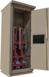
Rex Power Magnetics neutral grounding transformers provide a controlled ground reference for three-phase systems that do not naturally have a neutral, especially ungrounded or delta-connected networks. These grounding transformers are often referred to as a ground transformer in the field because their core function is to establish a stable neutral point and give ground fault current a defined path, helping protection respond in a more predictable way.
By creating that neutral point, neutral grounding transformers help reduce the risks that come with uncontrolled ground faults, including excessive stress on insulation, cables, switchgear, and connected equipment. When coordinated with the site grounding method, they support safer operation, improved system stability, and more consistent relay and breaker performance during line-to-ground fault events.
Rex Power Magnetics offers multiple configurations, including the zig-zag grounding transformer, a widely used design that forms a stable neutral reference without traditional voltage transformation and can perform well in systems with non-linear loads. Whether you need a standard ground transformer or a zig-zag design, contact Rex Power Magnetics, and we will help you select the right grounding transformers based on system voltage, grounding approach, fault duty requirements, and installation conditions.
| Type | Zig-Zag or Wye-Delta Connected |
| Rating | Continuous and Short Time Neutral Current Ratings (2, 5, 10 and 30 seconds) |
| Voltage Class | up to 46kV (250kV BIL) |
| Cooling | Air Cooled (ANN / AN) |
| Frequency | 60Hz |
| Conductors | Copper (Cu) or Aluminum (Al) Windings |
| Grounding | Solid or Resistance Grounded |
| Temperature Rise |
|
| Insulation System |
|
| Sound Level | Meets NEMA ST-20 |
| Enclosure Type | Type 1, 2, 3R, 4, 4X or 12 |
| Enclosure Finish | ANSI/ASA 61 Grey |
| Warranty | 12 Months (See Warranty and Limitations) |
| Quality System | ISO 9001:2015 Quality Management System |
| Certifications |
|
| Reference Standards |
|
| Optional Features |
|
Distribution Transformer Catalog (English)
Distribution Transformer Catalog (French)
A grounding transformer provides a neutral point for grounding a three-phase power system that otherwise operates without a direct neutral connection. It establishes a return path for ground fault currents and stabilizes system voltages during unbalanced or fault conditions. Rex Power Magnetics grounding transformers are designed to maintain system safety, minimize transient overvoltages, and ensure compliance with electrical grounding standards in industrial, utility, and renewable power systems.
Grounding limits voltage rise during line-to-ground faults, protects equipment insulation, and improves system protection coordination. Without a grounded neutral, faulted systems can experience overvoltages that endanger personnel and equipment. A grounding transformer provides a controlled path for zero-sequence currents, helping maintain voltage balance across all phases. It also enables the proper operation of protective relays and overcurrent devices, ensuring rapid fault detection and isolation.
In many systems, a neutral grounding resistor (NGR) is connected between the grounding transformer’s neutral point and ground to limit fault current to a safe, predetermined level. This configuration—known as resistance grounding—reduces damage during ground faults and allows continued operation until corrective action is taken. Rex Power Magnetics grounding transformers can be supplied with or without integrated NGRs, depending on the system’s protection scheme and coordination requirements.
A zig-zag grounding transformer has two half-windings on each core leg. Each half is connected in series with a half on the adjacent leg, wound in the opposite sense, and the three series pairs are joined at a common point that becomes the neutral. Under normal balanced (positive-sequence) voltage the two halves on each leg carry currents that do not cancel, so the winding behaves like a shunt magnetizing branch: the impedance is the full magnetizing impedance of the core and the unit draws only a small exciting current.
During a line-to-ground fault the neutral current divides into three equal, in-phase (zero-sequence) components, one per phase. On each leg the two halves now carry equal currents in opposite directions, so their magnetomotive forces cancel, no zero-sequence flux is set up in the core, and the only impedance left is the leakage reactance between the two halves. That leakage impedance is small, which is why the zero-sequence impedance of a zig-zag unit is low and the fault current is set by the neutral grounding resistor rather than the transformer. The Wye vs. Delta and 3-Phase Transformer Wiring articles in the Knowledge Hub show the connection diagrams.
A Rex grounding transformer draws minimal current during normal operation, primarily magnetizing current and any neutral current caused by system imbalance or harmonics. Operating costs are mainly determined by continuous no-load core losses.
Technically yes, however both the Canadian Electrical Code and the NEC restrict impedance-grounded systems to installations that do not serve line-to-neutral loads, so a resistance-grounded grounding transformer can never double as a 4-wire source. Where 120 V or 277 V or 347 V loads are needed from a delta bus, the usual solution is a separate delta-wye general purpose isolation transformer with its own solidly grounded neutral, and a Rex grounding transformer on the delta bus for fault detection. State the intended line-to-neutral load on the Product
In a Rex wye-delta grounding transformer, the grounded-wye winding establishes a neutral point, while the closed delta winding provides a circulating path for zero-sequence current during ground faults, helping prevent core saturation.
The delta winding is not typically used to supply auxiliary power, although it can power control equipment when designed for that purpose. Because the delta is a fully rated winding, it can be brought out to terminals and used to supply a small station-service or control load, which is one reason the wye-delta configuration is chosen for utility and generator applications. Doing so changes the rating basis: the transformer must carry the auxiliary kVA continuously and the short-time fault duty on top of it, and the two must be stated separately on the order. Rex builds wye-delta units to 46 kV class with the delta rated to suit.
The transformer rating depends on system line-to-line voltage, desired ground fault current, and allowable duration of the fault. Continuous-duty grounding transformers are rated for steady-state unbalanced currents, while short-time-duty designs are rated for high-current, short-duration faults. Rex Power Magnetics engineers assist in determining the appropriate kVA rating, connection type, and impedance value to ensure optimal system grounding performance and protection.
The two most common designs are zig-zag and wye-delta configurations.
Rex Power Magnetics offers both configurations, depending on system voltage, fault level, and application requirements.
Rex rates grounding transformers by neutral current and duration rather than by a load kVA, because the unit carries no load. The conventional short-time kVA, used in IEEE C57.32 and on the nameplate, is the product of system line-to-neutral voltage and rated neutral current.
Take a 13.8 kV delta bus to be low-resistance grounded at 200 A for 10 seconds. Line-to-neutral voltage is 13,800 / √3 = 7,967 V. The three-phase short-time rating is 7,967 V × 200 A = 1,593 kVA for 10 seconds, or 531 kVA per phase, since each phase leg carries 200 / 3 = 66.7 A of zero-sequence current at line-to-neutral voltage.
That figure is not the physical size of the transformer. A winding only has to survive 1,593 kVA thermally for 10 seconds, so its equivalent continuous rating is a small fraction of that number; IEEE C57.32 provides the basis for converting a short-time rating to an equivalent continuous design, and Rex applies it in the coil design. What matters to the purchaser is that the nameplate states rated neutral current, rated time, continuous neutral current and system voltage. The Transformer Rating Explained article and the Calculators page cover the voltage and current arithmetic.
Rex offers both on its grounding transformers, and the choice turns on the duty. For a short-time rated unit, the winding must absorb the I²t of the fault without exceeding its temperature limit. Aluminum has about 61 percent of copper’s conductivity and a lower volumetric heat capacity, so for the same short-time current it needs a larger conductor cross-section to stay within the limit. That is easy to accommodate on a low-current high-resistance grounded unit and less so on a 2 second, high-current solidly grounded design, where copper keeps the coil compact and stiff against electromagnetic forces.
Grounding transformers are used in ungrounded systems such as delta-connected generators, motor loads, or transformer banks. Typical applications include industrial distribution systems, renewable energy installations (wind or solar farms), and isolated power networks. They are also applied in generator step-up systems and mining operations where system grounding and overvoltage control are critical. Rex Power Magnetics designs grounding transformers for both utility and industrial-grade service, with ratings suitable for continuous or short-time duty.
Yes. Outdoor-rated grounding transformers are supplied with NEMA 3R or 4 enclosures and built to withstand environmental exposure. The polyester resin coating protects coils against humidity and contamination, while durable enclosures guard against rain, dust, and corrosion. Optional stainless steel or epoxy-coated housings are available for coastal, mining, or chemical applications. Proper grounding and ventilation ensure safe and reliable operation in all conditions.
A zig-zag grounding transformer has three phase terminals (H1, H2, H3) and a neutral terminal (H0 or N); there is no secondary. The phase terminals connect to the bus being grounded through the unit’s own fuses or breaker, using cable or bus rated for the system voltage class. The neutral terminal connects either directly to the station ground bus (solid grounding) or to one end of the neutral grounding resistor, whose other end is bonded to ground. The enclosure and core are bonded to the ground bus separately from the neutral circuit so that fault current never flows through the enclosure.
Rex grounding transformers are available in Type 1, 2, 3R, 4, 4X or 12 enclosures in ANSI 61 grey, with 304 or 316L stainless steel and custom colours as options. Type 1 is the indoor switchgear-room standard; Type 2 adds drip protection; Type 12 suits dusty plant floors; Type 3R is the outdoor default; Type 4 and 4X cover wash-down and corrosive sites, with 4X in stainless steel for coastal, marine duty and chemical plants.
For outdoor, humid or un-heated indoor installations, anti-condensation strip heaters are recommended.
A Rex grounding transformer establishes a neutral point on otherwise ungrounded medium-voltage collector buses in energy storage and solar installations, providing a controlled path for ground-fault current.
Its rating must account for the collector system’s capacitive charging current, inverter fault contributions, and required fault-clearing time. Rex offers grounding transformers up to 46 kV class, with outdoor enclosures, VPI/VPE or cast coil construction, and optional neutral current transformers for ground-fault protection.
Yes, and it is one of the most common low-voltage applications. Many older Canadian plants run 600 V delta distribution that is ungrounded, with ground-detection lamps as the only indication. Adding a low-voltage zig-zag grounding transformer with a neutral grounding resistor converts the bus to a high-resistance grounded system: the first ground fault produces a defined current of a few amperes that a relay can alarm on, the overvoltage hazard of an ungrounded system is removed, and production continues until the fault is located. The Canadian Electrical Code permits impedance grounding subject to conditions, including that no line-to-neutral loads are served and that ground-fault detection is provided, so the retrofit design must confirm those conditions.
A grounding transformer cannot be verified with the ratio test used on a load transformer, so the commissioning sequence differs. Rex recommends the following in addition to the general checks in the installation manual.
• Insulation resistance of the winding to ground and, on wye-delta units, between windings, with the neutral disconnected from the resistor so the winding is tested in isolation.
• Winding resistance per phase, compared with the test report to confirm connections and torque.
• Zero-sequence impedance measurement. Short the three phase terminals together, apply a single-phase test voltage between the shorted terminals and the neutral, and measure the current. Each phase carries one third of it, so Z_0 per phase = 3 V / I. Compare with the nameplate value.
• Neutral grounding resistor ohmic value and the integrity of its connection to ground.
• CT ratio and polarity on the neutral and phase CTs, and removal of the shorting screws only after the relay wiring is complete.
• Primary injection through the neutral circuit to prove the 51G or 59N relay picks up and trips the correct breakers.
• Bonding of enclosure and core, and clearance of ventilation louvres.
Record all readings as the baseline for maintenance. The Transformer Commissioning article gives the general procedure, and the Documentation page holds the manuals.
With the tie breaker closed, the two grounding transformers and their resistors are in parallel in the zero-sequence network. For a ground fault anywhere on the combined bus, each unit contributes its designed current, so the total fault current doubles: two 200 A low-resistance grounded sections become a 400 A system. Each transformer still carries only its rated 200 A, so the equipment is not overloaded, but the relaying, the arc-flash study and any equipment rated on the basis of 200 A ground-fault current must account for the higher value. On a high-resistance grounded system, paralleling halves the effective resistance and doubles the let-through, which is usually harmless but must remain within the continuous ratings.
Triplen harmonics (3rd, 9th, 15th) are zero-sequence, and a zig-zag grounding transformer offers them exactly the low-impedance path it offers to ground-fault current. On a bus with significant single-phase rectifier or drive load, third-harmonic current therefore circulates continuously through the grounding transformer neutral even though the system is healthy. Zig-zag units perform well in systems with non-linear loads, but the current still has to be included in the rating.
The effects are on the continuous rating and on losses. The RMS neutral current is the root-sum-square of fundamental unbalance and harmonic components, and it must stay within the unit’s continuous rating; a transformer specified with a nominal continuous rating of a few percent of its 10 second rating can be undersized on a heavily distorted bus. Harmonic current also raises eddy losses in the winding out of proportion to its RMS value, which is the same phenomenon that leads to K-factor ratings on K-factor rated transformers. On a resistance-grounded system the resistor sees the same harmonic current and heats accordingly.
Where the bus feeds drives, UPS rectifiers or LED lighting, provide Rex with the measured or estimated triplen content so the continuous rating and conductor can be set correctly. The Understanding Harmonics in Power Systems: IEEE 519 article explains the zero-sequence behaviour of triplen harmonics.
A grounding transformer that is working correctly is cool and quiet, so any change is diagnostic. The most common causes, roughly in order of likelihood, are:
• A standing ground fault. On a high-resistance grounded system a first fault may be alarmed and then ignored; the transformer and resistor carry let-through current continuously and warm up. Check the ground-fault relay and the resistor temperature.
• Harmonic zero-sequence current. Newly added drive or rectifier load pushes third-harmonic current through the neutral. Measure neutral current with a true-RMS meter and compare with the continuous rating.
• Voltage unbalance or an open phase upstream. A blown fuse on one phase of the grounding transformer’s own connection or of the bus feed leaves the zig-zag unbalanced, which raises current and hum sharply.
• Overvoltage. Bus voltage above nominal drives the core toward saturation, increasing exciting current, loss and magnetostrictive noise.
• Restricted ventilation from a blocked louvre, an enclosure placed against a wall or a failed strip heater thermostat.
Rex’s optional thermal sensing, thermometers and thermostat alarm contacts make the first indication a control-room alarm rather than a failed unit. The Transformer Humming Noise and Transformer Failures articles cover the underlying mechanisms.
The grounding transformer and its accessories form part of the protection circuit, so relay misbehaviour is often traced to them.
Failure to detect a fault usually means no current flowed in the neutral. Causes include an open neutral grounding resistor element, a blown fuse on one of the transformer’s phase connections (the zero-sequence path needs all three), a neutral CT left with its shorting screws in place after commissioning, a CT ratio or tap that puts the fault current below relay pickup, or a resistor in poor condition whose resistance has drifted upward. Periodic primary injection through the neutral circuit finds all of these.
Nuisance operation is usually a current that the relay sees but that is not a fault. On a heavily non-linear bus, third-harmonic neutral current can exceed a low 51G pickup; either raise the pickup within the coordination margin or use a relay with harmonic filtering. During a ground fault on another feeder, capacitive charging current of the healthy feeders flows through the transformer neutral, which is normal but can trip an incorrectly directional or over-sensitive scheme. Incorrect CT polarity in a residual scheme produces a false residual current under normal load. Confirm the relay settings against the transformer’s rated current and duration so that the relay clears within the rating. The Transformer Maintenance Checklist article includes the periodic protection checks.
Yes. Rex Power Magnetics offers complete customization for grounding transformers, including voltage class, configuration (zig-zag or wye-delta), kVA rating, fault current rating, and enclosure type. Optional features include neutral grounding resistors, temperature sensors, special insulation classes, and seismic or vibration-resistant mounting designs. Each custom transformer is fully engineered, built, and tested to the same rigorous standards as standard models to ensure precise performance and long-term reliability.
The grounding transformer specification table lists IEEE C57.32, CSA C22.2 No 47, CSA C9, IEEE C57.12.91 and NEMA ST-20, and the units are CSA certified and UL listed.
• IEEE C57.32 is the standard for neutral grounding devices, including grounding transformers, resistors and reactors. It defines the rating basis (rated neutral current, rated time, continuous current, rated voltage), the temperature limits for short-time duty, the test requirements and the nameplate content. It is the document a specification should cite for the rating.
• CSA C22.2 No 47 is the Canadian certification standard for air-cooled transformers; it governs construction, insulation, spacings and markings and is the basis of the CSA certification mark under the Canadian Electrical Code.
• CSA C9 is the Canadian dry-type transformer performance standard, covering test methods and performance requirements.
• IEEE C57.12.91 is the test code for dry-type distribution and power transformers, which supplies the procedures for resistance, loss, impedance, dielectric and temperature tests.
• NEMA ST-20 sets the sound level limits for dry-type transformers.
The installation itself follows the grounding sections of the Canadian Electrical Code (and in Ontario, Reg. 404/12 adopting it) or the NEC. Certification details are on the Certifications page, and the Power Transformer Testing article explains how the test standards are applied.
Because a grounding transformer has no load winding, the routine test sequence is adapted from IEEE C57.12.91 and C57.32. The production tests normally reported are winding resistance per phase, connection and polarity check, no-load loss and exciting current at rated voltage, zero-sequence impedance measured by the shorted-phase method, and dielectric tests comprising applied voltage (hipot) on the winding to ground and induced voltage to verify turn-to-turn insulation. For wye-delta units, ratio and applied voltage between windings are added. Each unit ships with a production test report.
Optional type tests worth considering are a temperature-rise test where the continuous rating is significant, for example on high-resistance grounded units that carry full let-through continuously or units with auxiliary load; a lightning impulse test to the specified BIL for medium voltage units where the unit is outdoors or exposed to overhead lines; a short-time current test or a calculated thermal demonstration of the rated neutral current and duration; and a sound level test to NEMA ST-20 for indoor installations near occupied areas. Type tests add time and cost and should be specified where the project requires the evidence rather than by default.
Test reports are supplied through the Documentation process, and the Power Transformer Testing and Partial Discharge in Dry-Type Transformers articles explain what each test demonstrates.
A dry-type grounding transformer is low maintenance, but because it spends years idle and then must perform for a few seconds, the maintenance plan should verify readiness rather than wear. A reasonable annual routine, with the unit de-energized and the bus isolated, is:
• Visual inspection of coils for dust, tracking, discolouration or resin cracking, and cleaning by vacuum or dry air.
• Insulation resistance test of the winding to ground, trended against the commissioning value.
• Check of all phase, neutral and ground connections for torque and discolouration.
• Measurement of the neutral grounding resistor and inspection of its elements and connections.
• Functional test of thermostat alarm and trip contacts and of strip heaters.
• Secondary injection or primary injection of the ground-fault relay through the neutral CT.
• Confirmation that ventilation openings and enclosure gaskets are intact.
After every ground fault that the transformer has carried, inspect the unit before returning the bus to normal duty: look for signs of overheating on the neutral lead and resistor, confirm the resistor value, and check the winding resistance if the fault was near or beyond the rated duration. A transformer that has carried repeated faults at its rated duty has experienced thermal cycles that a load transformer never sees. The Rex installation and maintenance manual and the Transformer Maintenance Checklist article give the general procedures.
Sunday, 15 February 2026
Proper grounding and bonding are fundamental to the safe and reliable operation of ...
Friday, 5 December 2025
Transformer grounding is one of the most critical aspects of electrical system design. ...