Harmonic Mitigating Transformers: How to Improve Power Quality
Modern electrical systems contain a growing concentration of non-linear loads — servers, UPS systems, LED lighting, computers, and variable-frequency drives. These devices draw current in pulses rather than smooth sine waves, creating harmonic distortion that travels through distribution systems and increases transformer heating, reduces efficiency, and stresses upstream equipment.
While K-rated transformers are designed to withstand the heating effects of harmonic currents, they do not reduce the distortion itself. Harmonic Mitigating Transformers (HMTs), by contrast, use engineered winding configurations and phase-shift techniques to actively reduce specific harmonic orders, improving upstream power quality and reducing stress across the system.
This article explains how HMTs work, where they are most effective, and how they differ from other harmonic solutions.
Harmonic Distortion in Modern Electrical Systems
Non-linear loads distort current waveforms, producing frequencies that are integer multiples of the fundamental (60 Hz). These harmonic currents adversely affect transformer operation.
Common characteristics include:
- Triplen harmonics (3rd, 9th, 15th) add in the neutral and lead to elevated neutral current.
- 5th and 7th harmonics increase stray flux and cause supplementary eddy-current heating.
- Total Harmonic Distortion (THDi) makes upstream voltage distortion worse under heavy non-linear loading.
- Typical sources include: VFDs, UPS systems, server racks, LED lighting, EV chargers, and switch-mode power supplies.
Without proper mitigation, these harmonics can produce excess transformer heating, nuisance tripping, reduced system capacity, and abnormal neutral conductor loading.

What Is a Harmonic Mitigating Transformer?
A Harmonic Mitigating Transformer is a dry-type transformer engineered to cancel or redirect harmonic currents using specially designed winding configurations, phase shifts, and zero-sequence impedance control.
A Key distinction with K-rated transformers is that HMTs reduce harmonic distortion while K-rated transformers only survive it.
HMTs do not absorb harmonics like a passive filter; instead, they use vector and phase relationships within the transformer windings to prevent additive harmonic currents from flowing into the upstream system.
How Harmonic Mitigating Transformers Work
The effectiveness of an HMT depends on winding geometry, core design, and engineered phase displacement. While the details vary by manufacturer, most HMTs employ three primary mechanisms:
Triplen Harmonic Reduction
Triplen harmonics (3rd, 9th, 15th) are zero-sequence components and naturally accumulate in the neutral. HMT winding schemes such as zig-zag, delta-zig-zag, or special dual-secondary configurations redirect or cancel these triplen currents, reducing neutral overloading.
Cancellation of 5th and 7th Harmonics
When two secondary outputs are phase-shifted (e.g., 0° and 30°), the 5th and 7th harmonic currents produced by separate load banks become 180° out of phase and cancel.
Reduced Stray Losses Through Magnetic Design
HMTs incorporate:
- Optimized core geometry
- Reduced zero-sequence impedance
- Special winding placement
- Controlled flux paths
These features limit leakage flux and minimize higher-frequency eddy-current heating.
The result is a transformer that runs cooler and produces lower upstream current distortion — without filters, reactors, or active electronics.
Types of Harmonic Mitigating Transformers
HMTs are available in several configurations depending on the harmonic profile of the installation.
Triplen-Canceling HMTs
Designed for environments dominated by single-phase electronic loads (offices, IT rooms). They target triplene harmonic reduction (3rd, 9th, 15th) and are used where high neutral current is a concern.
Phase-Shifted / Multi-Pulse HMTs
Provide a deliberate displacement between secondary outputs (e.g., 30° or 15°). When loads are divided appropriately, the 5th and 7th harmonics cancel naturally.
Ideal for:
- VFD-intensive facilities
- UPS plants
- Data centers with distributed non-linear loads
- Dual-Output HMTs
Provide two harmonically complementary outputs, each feeding separate panels. Triplen and non-triplen harmonics partially cancel upstream. Useful where no single load dominates but overall THDi needs reduction.
Benefits of Harmonic Mitigating Transformers
HMTs provide several system-wide advantages, described below in narrative form to maintain flow.
Lower Neutral Currents
By preventing triplen harmonics from accumulating in the neutral, HMTs significantly reduce neutral conductor heating and the risk of overload in 4-wire systems.
Reduced Transformer Heating
Harmonics increase stray and eddy-current losses. With an HMT, these losses are minimized by design, allowing the unit to operate cooler and more efficiently.
Improved Power Quality Upstream
Lower harmonic current flow results in reduced voltage distortion, benefiting sensitive equipment and supporting better PCC (Point of Common Coupling) compliance.
Higher Usable System Capacity
When harmonics are reduced, protective devices and conductors experience lower RMS current, freeing capacity for additional loads.
Extended Equipment Life
Lower temperatures and reduced harmonic stress improve the longevity of both the transformer and connected equipment.
Support for IEEE 519 Compliance
While HMTs do not guarantee compliance, they significantly improve harmonic performance at service entrances and distribution points.
HMTs vs. K-Rated Transformers
This distinction is critical for specifiers:
- K-Rated Transformers
- Harmonic Mitigating Transformers
- Designed to withstand harmonic heating
- Designed to reduce harmonic currents
- Do not change THDi or neutral loading
- Actively reduce harmonic distortion
- Increase reliability under distorted loads
- Improve upstream power quality
A K-rated transformer is appropriate where harmonic content is unavoidable but mitigation is not required. An HMT is appropriate where neutral currents, voltage distortion, or system losses must be reduced.
Application Considerations
Harmonic mitigating transformers should be selected based on a measured or well-characterized harmonic profile. They are most effective in environments where:
- Single-phase electronic loads dominate (triplen issues)
- Multiple VFDs or UPS systems create 5th and 7th harmonic clusters
- Facilities must meet power-quality standards
- Neutral conductors or feeders are running hot
- Upstream voltage distortion limits are being approached
Designers must consider load distribution, phase balance, grounding method, transformer connections, and the presence of other harmonic mitigation equipment (filters, reactors, active solutions). Proper system analysis ensures the HMT performs as intended.
Rex Power Magnetics Perspective
Rex Power Magnetics engineers and manufactures a full range of Harmonic Mitigating Transformers, including:
- Zig-zag and delta-zig-zag configurations for triplen mitigation
- Dual-secondary and phase-shifted outputs for 5th and 7th harmonic cancellation
- Reduced zero-sequence impedance designs for lower neutral current
- Optimized magnetic and winding construction to minimize stray losses
Each HMT is sized and configured based on the specific harmonic spectrum of the application. Rex engineers support consultants and end users with harmonic assessment, load evaluation, and transformer selection to ensure measurable power-quality improvement.
Conclusion
Harmonic mitigating transformers are an effective, passive solution for reducing harmonic currents and improving overall power quality. They provide benefits such as lower transformer heating, reduced neutral loading, improved upstream voltage quality, and better utilization of electrical system capacity.
By combining engineered winding configurations with deliberate phase displacement, HMTs offer a robust way to handle the growing harmonic challenges of modern electrical installations. When selected and applied correctly, they outperform traditional approaches such as K-rated transformers in both performance and long-term system reliability.
Transformer Clearance Requirements: Ensuring Safe and Code-Compliant Installations
Clearances around dry-type transformers play a central role in ensuring proper operation, electrical safety, and compliance with installation codes. Because dry-type transformers rely entirely on air movement for cooling, any obstruction around the unit can affect temperature rise and longevity. At the same time, electrical codes in both Canada and the United States establish mandatory working space and approach distances to maintain safe access and prevent exposure to energized components.
In Canada, transformer installation requirements fall under the Canadian Electrical Code (CEC). In the United States, they are guided by the National Electrical Code (NEC). These codes form the foundation for safe installation practices, while manufacturer instructions provide transformer-specific ventilation and clearance requirements. For full compliance, both must be followed.
Why Clearances Matter
Transformer clearances serve three important functions:
Thermal performance: Adequate spacing ensures airflow is not obstructed, preventing overheating.
Electrical safety: Working clearances provide safe approach distances and protect personnel.
Serviceability: Sufficient access allows for inspection, maintenance, and troubleshooting.
Failure to maintain proper spacing can lead to elevated temperatures, nuisance tripping, reduced insulation life, and potential code violations.

Thermal and Ventilation Clearance
Dry-type transformers dissipate heat through natural or forced air circulation. Maintaining ventilation clearance around the transformer ensures air can enter, pass across heated surfaces, and exit freely.
Manufacturers typically specify minimum distances around ventilated surfaces. As a general guideline:
- 150–300 mm (6–12 inches) is commonly recommended around ventilated sides
- Greater spacing may be required for larger kVA ratings or enclosed installations
- Airflow paths must remain unobstructed, including top and bottom ventilation openings
While these values support airflow around the unit, room-level ventilation is equally important. In mechanical or electrical rooms, transformer heat contributes to the ambient temperature. Without adequate room ventilation, internal temperatures may exceed design assumptions even when unit-level spacing is adequate.
As a result, the design of transformer installations often includes:
- Air intake and exhaust openings
- Mechanical or forced room ventilation
- Avoidance of dead-air pockets or recirculation zones
- Electrical Safety Clearances
Electrical safety spacing is defined by local electrical code, not the manufacturer. These clearances ensure that qualified personnel have safe access to equipment and do not come into contact with energized components. Working space must comply with:
Typical minimums include:
- 1 m (3.3 ft) of clear space in front of electrical equipment
- Sufficient width equal to equipment or at least 750 mm
- Headroom of 2 m (78 in.)
These requirements apply, even if the transformer is fully enclosed, because the space is required for servicing associated electrical equipment.
Indoor Installations
Indoor installations must consider:
- Ventilation clearance from walls or partitions
- Total heat load within the electrical room
- Building code requirements for combustibility and fire protection
- Space for cable entry, bending radius, and connection access
Confined rooms may require engineered airflow solutions or additional clearance beyond minimum manufacturer recommendations.
Outdoor Installations
Even with weatherproof enclosures (e.g., NEMA 3R, 4, 4X), outdoor transformers still require ventilation spacing. Installers should maintain distance from:
- Walls and architectural structures
- Fences and screens
- Vegetation or debris
- Snow accumulation zones
Outdoor installations must also consider building code requirements related to elevation, drainage, seismic anchoring, and wind loading.
Fire Safety Considerations
Dry-type transformers do not contain oil and are classified as non-combustible electrical equipment. However, they still generate heat during operation, and clearances help prevent heat accumulation near adjacent construction materials. In some cases—particularly for large power transformers in enclosed spaces—building and fire codes may require fire-rated rooms, barriers, or enclosures. NEC 450.21 and corresponding sections of the CEC establish requirements for transformer placement relative to combustible construction, ventilation ducts, and fire separation.
Noise, Vibration, and Clearance Interaction
Clearances can influence how transformer sound is perceived. When transformers are installed too close to walls or rigid surfaces, sound reflection can increase perceived noise levels. Adequate spacing helps minimize resonance effects, and supplemental measures such as vibration isolators or sound-attenuating enclosures can be applied when necessary.
Codes, Standards, and Manufacturer Requirements
The local electrical code—CEC in Canada and NEC in the United States—sets the minimum mandatory requirements for transformer installation. These rules govern electrical safety, working space, guarding of live parts, fire protection, and ventilation.
Industry standards such as CSA C9, IEEE C57.12.01, IEEE C57.12.91, and NEMA ST-20 provide additional context on transformer design, testing, and performance but do not replace code requirements for installation.
Manufacturer installation instructions remain an equally important part of compliance. They specify airflow requirements, minimum clearances for ventilation, positions requiring access, and any restrictions related to enclosure openings, fan placement, or top/bottom airflow paths. These instructions ensure the transformer can operate within its thermal design limits and must always be followed to maintain warranty and performance expectations.
Conclusion
Clearances play a vital role in the safe and reliable installation of dry-type transformers. They support proper ventilation, protect personnel, simplify maintenance, and ensure compliance with local electrical codes. By coordinating manufacturer guidelines with the applicable installation code—CEC in Canada or NEC in the United States—designers and installers can maintain thermal performance, extend transformer life, and achieve a trouble-free installation.
Understanding Transformer Insulation Classes: Importance, Types, and Standards
The insulation system is one of the most critical components in a dry-type transformer. It determines how much heat the transformer can safely handle, how long it will last, and how reliably it performs over time.
Insulation classes define the thermal endurance of materials used within the transformer — the winding insulation, core barriers, and impregnation systems. Understanding these classes and their relationship to temperature rise is essential for specifying transformers that deliver long service life under real-world conditions.
Modern dry-type transformers use Vacuum Pressure Impregnated (VPI), Vacuum Pressure Encapsulated (VPE), or cast-coil insulation systems, typically rated for Class R (220 °C) or Class H (180 °C) operation. But how those insulation systems are applied — not just their temperature limit — largely determines transformer longevity.
What Is an Insulation Class?
An insulation class is a thermal rating that indicates the maximum total temperature the transformer’s insulation system can safely withstand over its expected lifetime.
This total temperature is made up of:
- Ambient temperature (usually 30 °C)
- Average winding temperature rise above ambient
- Hot-spot allowance, accounting for localized heating
For example, a Class R insulation system rated for 220 °C may operate with a 150 °C temperature rise above 30 °C ambient and still remain within its limit. Exceeding these limits accelerates insulation aging exponentially, reducing life expectancy and potentially leading to premature failure.
Common Insulation Classes in Dry-Type Transformers
Dry-type transformers are built to recognized standards such as IEEE C57.12.01, IEEE C57.12.91, and CSA C9. The most common insulation classes are summarized below:

Standard for VPI and VPE dry-type transformers
In modern manufacturing, Class R insulation systems are standard for VPI and VPE dry-type transformers, providing superior thermal margin and durability. Class H systems are typically used in cast-coil designs, where epoxy encapsulation offers enhanced dielectric and environmental protection.
The Relationship Between Temperature and Transformer Life
The relationship between operating temperature and insulation life is exponential — for every 10 °C increase beyond the rated insulation temperature, the expected insulation life roughly halves.
This relationship underscores the value of thermal headroom: operating a transformer well below its insulation limit significantly extends its service life. For example:
- A transformer built with Class R (220 °C) insulation but designed for a 150 °C temperature rise under standard ambient conditions may easily outlast its nominal 25-year life expectancy.
- If that same transformer is instead designed for a 115 °C rise, using the same Class R insulation, its expected lifespan can more than double, due to reduced thermal stress. This approach — pairing higher-class insulation with lower operating temperature — provides reserve capacity against thermal stress caused by ambient extremes, harmonics, or limited ventilation.
Why Higher Insulation Class at Lower Temperature Rise Extends Life
Several real-world conditions can elevate operating temperature beyond design assumptions. Using a higher insulation class with a conservative temperature rise allows transformers to tolerate these stresses without accelerated aging:
High Ambient Temperature
Standard ratings assume 30 °C average ambient, but installations in mechanical rooms, rooftops, or industrial settings may experience sustained ambients of 40–50 °C. The additional thermal margin of Class R insulation preserves life expectancy under these conditions.
High Operating Altitude
At elevations above 1,000 m (3,300 ft), air density decreases, reducing cooling efficiency. A transformer with higher insulation class and lower designed rise compensates for reduced heat dissipation, maintaining safe winding temperatures.
Harmonic Distortion
Non-linear loads such as VFDs, UPS systems, and LED lighting introduce harmonic currents that increase conductor and stray losses. These additional losses raise winding temperatures beyond nameplate rise. A higher insulation class ensures that the system remains within thermal limits even under distorted load conditions.
Overload or Intermittent Duty
Some applications experience short-term overloads or cyclic loading. Transformers built with higher-class insulation can accommodate temporary temperature excursions without accelerated degradation.
Restricted Ventilation or Enclosure Effects
Enclosed or compact installations may have reduced air flow. The additional margin provided by Class R insulation protects the transformer under less-than-ideal cooling conditions.
Components of the Insulation System
A dry-type transformer’s insulation system includes several integrated elements designed to manage electrical stress, mechanical forces, and heat:
- Conductor insulation: Enamel coatings or fiberglass wraps on copper or aluminum windings.
- Inter-turn and inter-layer insulation: Nomex®, mica, or glass-fiber materials for dielectric separation.
- Core-to-coil barriers: Rigid insulation boards that provide clearance and support.
- Impregnation or encapsulation: Resin (VPI/VPE) or epoxy (cast-coil) systems that bond and protect windings.
Each component is chosen to ensure compatibility with the target insulation class and to maintain integrity throughout thermal cycling.
Selecting the Appropriate Insulation Class
Transformer insulation class should be selected based on both application environment and design philosophy:
- Class 220 (R) — Standard for VPI and VPE dry-type transformers. Provides superior thermal endurance, long life expectancy, and tolerance for non-ideal conditions (high ambient, altitude, harmonics).
- Class 180 (H) — Used in cast-coil units where encapsulated construction provides moisture and contaminant protection.
- Class 155 (F) — Appropriate for smaller or specialty transformers with light thermal loading.
- Designing for a lower rise (e.g., 115 °C) using Class 220 insulation ensures a cooler operating temperature, longer life, and greater reliability margin — a best practice increasingly adopted across critical infrastructure, industrial, and commercial projects.
Rex Power Magnetics Approach
At Rex Power Magnetics, dry-type transformers are engineered with 220 Class insulation systems for all VPI and VPE designs, and 180 Class systems for cast-coil constructions.
Our design philosophy prioritizes long-term thermal reliability through:
- Controlled VPI and VPE resin impregnation ensuring complete dielectric coverage.
- Thermal modeling and testing per CSA C9 and IEEE C57.12.01.
- Design optimization for lower temperature rise operation to extend insulation life.
- Engineering consultation for installations with elevated ambient, altitude, or harmonic content.
The result is a transformer that runs cooler, lasts longer, and remains stable under real operating stresses.
Conclusion
Transformer insulation class defines not just a temperature rating, but the foundation of its reliability and life expectancy.
By combining higher temperature-class insulation systems with lower design temperature rise, engineers can achieve significantly longer transformer life — even in high ambient, high-altitude, or harmonic-rich environments.
At Rex Power Magnetics, we integrate Class R and Class H insulation systems with precision VPI, VPE, and cast-coil manufacturing processes to ensure every transformer delivers dependable, long-term performance — under any conditions.
Transformer Inrush Current: Causes, System Effects, and Mitigation
Updated: August 17th, 2026
When a transformer is energized, the current drawn from the source is not always close to its normal no-load value. Under an unfavourable combination of switching instant and residual core flux, the magnetic core can be driven deeply into saturation. The transformer then draws a large, asymmetric magnetizing current known as transformer inrush current.
Inrush is an expected energization transient, not evidence that the transformer is overloaded or faulted. It can nevertheless operate fuses or circuit breakers, restrain or challenge protective relays, and produce a temporary voltage disturbance. The practical task is therefore not to eliminate every transient, but to understand the credible inrush duty and coordinate the transformer, source, switching equipment, and protection around it.
What Causes Transformer Inrush Current?
Transformer voltage and core flux are linked by electromagnetic induction. In simplified terms, core flux is proportional to the time integral of the applied winding voltage. During steady operation, the positive and negative volt-seconds of the alternating voltage produce a balanced flux waveform around the core’s normal operating point.
At energization, that balance has not yet been established. If voltage is applied at an unfavourable point on the waveform, the first volt-second interval can drive flux largely in one direction. A de-energized transformer may also retain residual flux. When it is in the same direction as the new transient flux, the combined value can move beyond the core’s normal operating range.
The magnetizing inductance falls sharply as the core enters saturation. Current then rises until it is limited by the source impedance, winding resistance, leakage reactance, and the nonlinear magnetic characteristics of the core. This is why a transformer can draw several multiples of rated current even when its secondary is open and no load power is being delivered.
For a simple single-phase case, closing near a voltage zero can produce the largest flux offset, while closing near a voltage peak can reduce it. A three-phase transformer is more complicated. The pole-closing sequence, winding connection, core construction, residual flux in each leg, and phase relationship all affect the result, and the best closing instant is not necessarily identical for every pole.

Which Factors Determine the Magnitude and Duration?
There is no universal inrush multiplier or decay time. Rules of thumb can support early screening, but protection settings and voltage-dip studies should use information suited to the actual transformer and system.
Residual flux is one of the most influential variables because it changes the flux starting point at the next energization. The switching instant and pole scatter determine how the applied volt-seconds combine with that residual flux. Supply voltage also matters: operation above rated volts per hertz moves the core closer to saturation before transient offset is considered.
Core geometry, joint construction, material, normal operating flux density, air gaps, and winding arrangement shape the saturation characteristic. No single feature, such as grain-oriented steel or step-lap construction, guarantees low inrush by itself. A low-loss core design and a low-inrush design involve related but not identical trade-offs and must be evaluated as a complete magnetic design.
The system determines how much current can flow after saturation begins. A strong source with low upstream impedance can supply a higher peak. A weaker source limits current more strongly, but the same inrush flowing through its greater impedance may produce a more serious voltage dip. Transformer impedance also contributes to the current path, although nameplate percent impedance alone does not describe the nonlinear magnetizing branch responsible for inrush.
Transformer rating is not a sufficient predictor. Larger units can produce substantial absolute current, but the multiple of rated current does not follow a simple kVA rule. The energized winding also matters. In applications such as reverse feeding a transformer, the protective device can see a different inrush duty from that assumed for normal forward energization.
What Does the Inrush Waveform Look Like?
Inrush current is normally nonsinusoidal and strongly asymmetric. One polarity can contain large, narrow current peaks as the core enters saturation, while the opposite half-cycle is much smaller. The waveform usually falls quickly during the first cycles and then decays more gradually as resistance and system losses remove the flux offset. A smaller transient component can remain after the visually dominant peak has passed, so duration should be judged against the relevant protection curve rather than by one fixed time value.
Magnetizing inrush often contains significant even-harmonic content, particularly second harmonic. Transformer differential protection has historically used harmonic restraint or blocking to remain secure during energization. However, second-harmonic content is not constant and may be lower for some transformer designs or switching conditions. Modern protection may combine harmonic quantities with waveform, differential, voltage, or other logic. Relay settings should therefore follow the protection study and the device manufacturer’s application guidance, not a universal second-harmonic threshold.
Inrush must also be distinguished from load starting current and internal fault current. Motor starting occurs because a connected motor draws high current while accelerating. Transformer inrush occurs in the magnetizing branch when core flux is established, even with the secondary unloaded. An internal fault can also create high current, but protection cannot simply assume that every large current immediately after closing is harmless inrush.
How Should Inrush Current Be Estimated?
An exact transformer inrush current calculation requires more than rated kVA and voltage. A credible model may include the core’s nonlinear magnetization characteristic, residual flux, winding resistance and leakage reactance, source short-circuit strength, system X/R ratio, breaker pole-closing times, connection, grounding, and other transformers already connected to the bus.
For routine distribution applications, manufacturer energization data and the protective device’s time-current curve may be enough to confirm ride-through. The inrush envelope should be checked against the fuse minimum-melting curve or breaker and relay characteristics while preserving the required response to overloads and faults. Rex’s guide to transformer fuse sizing explains why full-load current is only the starting point for this coordination.
Electromagnetic transient studies are appropriate when the source is weak, the transformer is large relative to the system, several units may be energized together, voltage-sensitive loads share the bus, or switching occurs frequently. EMTP or PSCAD can evaluate alternative closing conditions rather than one deceptively precise result. CIGRE Technical Brochure 568 provides guidance on voltage dips, temporary overvoltages, modelling, and mitigation.
How Can Inrush Affect the Electrical System?
The most visible consequence is nuisance operation. A fuse, circuit breaker, or overcurrent relay may respond if its pickup and time characteristics do not provide enough margin above the credible inrush envelope. Simply increasing the protective-device rating is not a complete solution because the revised device must still protect conductors, meet applicable code requirements, interrupt the available fault current, and coordinate with transformer and downstream protection.
Inrush also creates a voltage drop across the source and feeder impedance. The resulting dip may reset controls, disturb contactors, affect variable-frequency drives, or cause lighting and electronic equipment to malfunction. A low-impedance source may permit a higher inrush current but maintain its bus voltage better; a weak source may supply a lower current yet experience a deeper voltage dip.
Energizing one transformer can also disturb transformers already connected to the same bus. The system voltage distortion and flux response can produce sympathetic inrush in an energized unit, extending the disturbance or involving protection beyond the transformer being switched. This interaction is particularly relevant when multiple transformers share a weak source.
The transient electromagnetic forces and sound can be noticeable, but inrush should not be treated as equivalent to a short circuit. Fault-current forces are normally the primary mechanical withstand concern. Frequent energization can still impose repeated duty on breakers, contactors, fuses, and transformer windings, so the intended switching frequency should be disclosed during specification.
How Can Transformer Inrush Be Reduced or Managed?
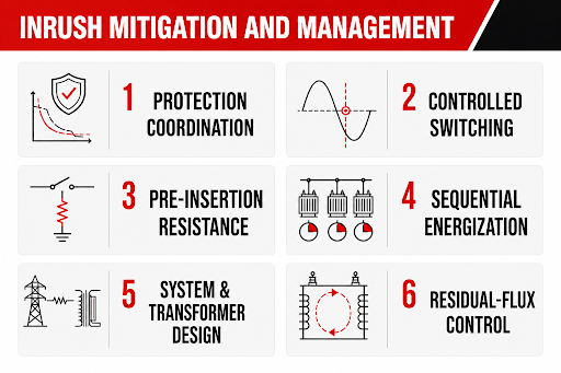
The correct method depends on whether the real problem is excessive current, unacceptable voltage dip, protection operation, or frequent switching. Several measures may be appropriate:
Protection coordination: Correct fuse, breaker, and relay characteristics allow normal inrush to pass while maintaining the required response to faults. This manages the consequence; it does not reduce the inrush itself. IEEE C37.91-2021 provides transformer-protection guidance within its stated scope and notes that some techniques may also be applied outside that scope.
Controlled switching: Point-on-wave closing can select pole-closing instants that reduce transient flux. The strongest schemes account for transformer connection, core behaviour, breaker operating scatter, and residual flux rather than relying on a fixed voltage angle.
Pre-insertion resistance: A switching device can insert resistance briefly during energization and bypass it after the transient has been limited. The resistor value, energy duty, insertion time, and switching sequence must be engineered for the application.
Sequential energization: Staggering multiple transformer energizations prevents their worst transients from occurring together. Disconnecting or minimizing downstream load does not eliminate magnetizing inrush, but it separates the core-energization event from simultaneous load pickup.
System and transformer design: Source configuration, feeder impedance, core flux density, transformer connection, and switching duty can be evaluated together. Adding a reactor or other impedance may reduce peak current, but it can also affect voltage regulation, losses, and normal operation.
Residual-flux control: Controlled de-energization or demagnetization can reduce uncertainty before the next closing operation. These techniques are generally reserved for applications where switching frequency or system sensitivity justifies the added equipment and control.
Information Needed During Specification and Commissioning
Inrush becomes easier to manage when it is treated as an application requirement rather than discovered during first energization. The transformer manufacturer and protection engineer should know the source voltage and short-circuit strength, upstream impedance, winding connection, grounding arrangement, intended energization side, breaker or contactor characteristics, switching frequency, connected transformer capacity, allowable bus-voltage dip, and sensitivity of other loads.
Commissioning should confirm that the installed transformer, tap position, protection settings, switching sequence, and system configuration match the study basis. Initial energization should follow an approved procedure and be observed by qualified personnel. Rex’s transformer commissioning guide covers the checks needed before a unit is placed in service.
Conclusion
Transformer inrush current begins with transient core flux, but its practical severity is determined by the complete electrical system. Residual flux and closing instant influence saturation; magnetic design shapes the current waveform; source impedance determines the current available and the resulting voltage dip; and protective-device characteristics determine whether the event causes an outage.
Rules of thumb are useful for screening, but they cannot replace transformer-specific data or a system study where energization duty is critical. Reliable operation comes from coordinating the transformer, source, switching method, and protection for the actual installation.
The Manufacturing Process of VPI/VPE Power Transformers: Understanding Vacuum Pressure Impregnation
In dry-type transformers, the insulation system is central to both electrical performance and mechanical reliability. It provides dielectric separation between windings, structural rigidity against electromagnetic forces, and thermal endurance during continuous operation.
Among the most proven and widely adopted insulation technologies in modern transformer design are Vacuum Pressure Impregnation (VPI) and Vacuum Pressure Encapsulation (VPE). These processes combine vacuum drying, resin impregnation, and controlled curing to produce robust, long-lasting insulation that can endure harsh electrical and environmental conditions.
This article explains the VPI and VPE manufacturing processes, their advantages, and how these technologies enhance transformer reliability and service life — particularly as applied in Rex Power Magnetics dry-type power transformers.

Overview of VPI and VPE Insulation Methods
Both VPI and VPE processes are designed to seal transformer windings within a high-dielectric resin system. The goal is to eliminate air and moisture from the insulation material and fill any microscopic voids that could lead to partial discharge, corona inception, or tracking under voltage stress.
Vacuum Pressure Impregnation (VPI):
In this process, dry-type transformer coils are placed inside a sealed chamber where a vacuum removes all trapped air and moisture. A low-viscosity polyester or epoxy resin is then introduced under controlled pressure, forcing the resin deep into the windings and insulation layers. After impregnation, the coils are baked in an oven to cure the resin into a solid, rigid dielectric structure.
Vacuum Pressure Encapsulation (VPE):
The VPE process extends the same principles but adds multiple impregnation and curing cycles. Each successive cycle builds an additional layer of resin, resulting in a thicker, more durable coating that provides enhanced protection against moisture, contaminants, and environmental exposure.
While both methods improve insulation performance, VPE is typically specified for harsh or outdoor environments, whereas VPI is optimal for indoor and controlled applications where high dielectric strength and low partial discharge are the primary requirements.
The Manufacturing Process — Step by Step
Coil Preparation
Manufacturing begins with precision winding of the transformer coils using copper or aluminum conductors. The windings are layered and insulated using high-temperature materials such as polyester, Nomex®, or fiberglass, depending on the insulation class.
Before impregnation, the coils are preheated to remove residual moisture and to ensure thermal expansion stability. The core and coil assembly is prepared for processing with carefully maintained clearances, insulation wrapping, and supports.
Vacuum and Pressure Impregnation
The prepared coils are loaded into a vacuum pressure chamber, a sealed steel vessel designed to handle both deep vacuum and positive pressure.
Vacuum Stage:
Air and moisture are drawn out of the insulation and winding spaces under deep vacuum. This stage ensures that all voids and capillaries are empty, allowing complete resin penetration in the next step.
Pressure Stage:
Once the vacuum cycle is complete, a carefully formulated insulating resin is introduced into the tank. Compressed air or inert gas pressure forces the resin into every pore and layer of the winding. Resin viscosity, temperature, and time are closely controlled to ensure consistent coverage without over-saturation.
The result is full impregnation of the coil — a uniform, void-free insulation matrix with high dielectric and mechanical strength.
Resin Curing
After impregnation, the coils are transferred to a temperature-controlled curing oven. The curing process cross-links the resin polymer, forming a hard, glass-like dielectric coating that bonds and stabilizes the entire coil assembly.
For VPE transformers, this curing step is repeated after each resin immersion cycle. The process builds multiple layers of protection, increasing the surface coating thickness and providing a superior barrier to humidity, chemicals, and pollutants.
Precise temperature control and curing time are critical to achieving consistent mechanical and dielectric properties. Over-curing can cause brittleness, while under-curing may leave residual volatiles that reduce insulation performance.
Finishing and Assembly
Once cured, the coils are cooled, cleaned, and inspected before being integrated into the transformer assembly. Core connections, terminals, temperature sensors, and enclosure fittings are installed according to design specifications.
At this stage, the transformer undergoes a complete series of factory acceptance tests to verify performance and compliance with standards, including:
- Insulation resistance and applied voltage tests
- Induced voltage and turns ratio verification
- Partial discharge measurements
- Temperature rise and sound level tests (as applicable)
Each test ensures that the impregnation and curing processes have produced a transformer that meets or exceeds mechanical and dielectric requirements.
Benefits of the VPI/VPE Process
The VPI and VPE methods offer distinct advantages in reliability, durability, and operational stability:
Superior Electrical Insulation:
Resin impregnation eliminates air gaps that could lead to corona discharge or tracking, providing a uniform dielectric medium with high breakdown strength.
Mechanical Integrity:
The cured resin bonds the winding and insulation materials into a solid mass, increasing structural rigidity and resistance to vibration and short-circuit forces.
Moisture and Contaminant Resistance:
Especially in VPE designs, the encapsulating resin layer shields the transformer from humidity, dust, and corrosive airborne particles.
Thermal Stability:
The impregnation materials are rated for high-temperature operation and repeated thermal cycling, ensuring long-term performance.
Low Maintenance and Noise:
Rigid windings and stable insulation reduce vibration and mechanical hum, while minimizing the need for maintenance in clean, ventilated environments.
Rex Power Magnetics Manufacturing Expertise
At Rex Power Magnetics, the VPI and VPE processes are conducted in controlled manufacturing environments using advanced vacuum and pressure systems. Each impregnation cycle is monitored for resin temperature, viscosity, and vacuum level to ensure repeatable quality.
Our VPE process incorporates multiple immersion and cure cycles, building a durable protective coating that meets the demands of outdoor, industrial, or high-contamination environments. In-house testing — including partial discharge and dielectric withstand — confirms the integrity of every insulation system before shipment.
Rex also customizes insulation formulations and curing profiles to meet specific customer or environmental requirements, ensuring optimal performance in every application.
Conclusion
The Vacuum Pressure Impregnation (VPI) and Vacuum Pressure Encapsulation (VPE) processes are at the heart of reliable dry-type transformer manufacturing. Through careful control of vacuum, resin impregnation, and curing, these methods produce insulation systems with exceptional dielectric strength, mechanical integrity, and moisture resistance.
By applying these processes with precision and consistency, Rex Power Magnetics ensures that each transformer — from low-voltage distribution units to medium-voltage power designs — delivers safe, efficient, and maintenance-free performance throughout its service life.
Understanding Losses in Transformers: Types, Causes, and Impact on Efficiency
Transformers are designed to operate with remarkable efficiency, often exceeding 98%. Yet even the best designs experience small but unavoidable energy losses whenever voltage and current flow through their magnetic and electrical paths. These losses manifest as heat, which affects performance, reliability, and lifecycle cost.
Understanding the types, causes, and magnitude of transformer losses is essential for optimizing performance and specifying units that balance energy efficiency with durability. Industry standards such as IEEE C57.12.01, CSA C802.2, and NRCan 2019 define acceptable loss levels and testing methods to ensure consistent, measurable performance across manufacturers.
This article explores the primary loss components—core, conductor, and stray—and explains how they influence transformer efficiency and long-term operating cost.
Core (No-Load) Losses
Core losses, also called no-load losses, occur whenever a transformer is energized, regardless of the load. They arise from the magnetization and demagnetization of the steel core with each alternating current cycle.
Two physical phenomena cause these losses:
Hysteresis Loss: As the magnetic field in the core reverses direction 60 times per second, the steel’s magnetic domains realign. The molecular friction created during this process consumes energy and produces heat.
Eddy Current Loss: Alternating magnetic flux induces circulating currents within the steel laminations. These currents generate localized heating that further contributes to no-load loss.
Core losses depend primarily on the magnetic properties of the steel and the flux density in the core. Using grain-oriented silicon steel, thin laminations, and optimized joint design (such as step-lap construction) significantly reduces hysteresis and eddy current effects.
Because no-load losses occur continuously whenever the transformer is energized, they represent a major portion of energy consumption in lightly loaded or continuously energized equipment.
Load (Conductor) Losses
Load, or conductor losses, occur when current flows through the transformer windings. They are proportional to the square of the load current and arise from the electrical resistance of the winding material—whether copper or aluminum. The fundamental principle is the same: current squared times resistance (I²R).
As current increases, conductor heating rises sharply. Winding material, cross-sectional area, temperature, and operating conditions all influence these losses. Transformers designed with larger conductor cross-sections or higher conductivity material exhibit lower resistive losses but at higher material cost and weight.
Conductor losses also vary with temperature. As winding temperature rises, resistance increases, resulting in slightly higher losses at full load. For this reason, test results are standardized to a 75°C reference temperature for comparison across manufacturers and materials.
Stray and Additional Losses
In addition to I²R losses, transformers experience stray losses caused by leakage magnetic flux that does not follow the intended path through the core. This flux induces eddy currents in nearby metallic parts—such as core clamps, tank walls, and structural supports—creating additional localized heating.
Other factors can add to stray losses:
Leakage Flux Coupling: Non-uniform magnetic fields around conductors induce circulating currents in adjacent metalwork.
Proximity and Skin Effects: At higher frequencies or in harmonic-rich systems, current tends to concentrate near conductor surfaces, increasing effective resistance.
Harmonic Currents: Non-linear loads such as VFDs and UPS systems generate harmonics that elevate both conductor and stray losses beyond standard design expectations.
Stray losses are usually small but can become significant in systems with high harmonic distortion or non-sinusoidal loading. IEEE C57.110 provides detailed guidance for evaluating these effects and applying appropriate derating factors.
Total Losses and Efficiency
A transformer’s total loss at any load point is the sum of its core, conductor, and stray losses. These losses convert directly into heat, reducing efficiency and increasing cooling demand.
Efficiency is defined as the ratio of output power to input power, expressed as a percentage. Because no-load losses are constant while load losses vary with current, transformer efficiency changes with load.
Most transformers reach their maximum (peak) efficiency at approximately 40% to 70% of rated load—where the variable and constant losses are balanced. Operating consistently above or below that range can result in increased losses and reduced overall efficiency.
Factors Affecting Transformer Efficiency
Transformer efficiency depends on both design and operational factors.
Material Quality and Design
- High-grade, grain-oriented core steel minimizes hysteresis and eddy current losses.
- Larger conductors or high-conductivity materials reduce resistive losses but increase cost and mass.
- Precision coil geometry and balanced magnetic design limit stray flux.
Operating Conditions
- Elevated ambient temperatures reduce cooling effectiveness and increase winding resistance.
- Unbalanced loading between phases can cause localized heating.
- Harmonic distortion raises apparent load and loss levels, even when RMS current remains within limits.
System Sizing and Loading
- Selecting a transformer appropriately sized for its expected loading profile is critical. Oversized transformers operate with higher no-load losses relative to useful load, while undersized units run hotter and age faster.
- Matching transformer capacity to the real load curve ensures both energy and cost efficiency.
Efficiency Standards and Regulatory Requirements
National efficiency regulations ensure that modern transformers contribute to energy conservation and environmental responsibility.
In Canada, Natural Resources Canada (NRCan) 2019 efficiency regulations establish minimum performance levels for dry-type distribution transformers under the Energy Efficiency Act. These requirements are harmonized with CSA C802.2, which defines test methods, reference conditions, and reporting procedures.
In the United States, the DOE 2016 Energy Conservation Standards define comparable limits. Both standards specify minimum efficiencies at rated voltage, frequency, and load conditions, ensuring consistency across the North American market.
Rex Power Magnetics designs and tests transformers to meet or exceed NRCan 2019 and DOE 2016 efficiency requirements, verifying compliance through certified performance testing at rated conditions.

Improving Efficiency Through Design and Application
While losses cannot be eliminated entirely, they can be minimized through engineering, materials, and proper system application.
Design Optimizations
- Use of high-permeability, low-loss core steel.
- Precision-engineered step-lap cores to reduce flux leakage and noise.
- Optimized winding geometry to minimize leakage flux paths.
- Selection of conductor material and size to balance cost and efficiency.
Application Best Practices
- Select transformers sized for typical (not peak) load conditions.
- Maintain clean ventilation and monitor operating temperature.
- Address harmonic distortion through filters or harmonic-mitigating transformers.
- Implement regular maintenance to prevent connection losses and overheating.
- An efficient transformer not only saves energy but also operates cooler, extending insulation life and improving overall system reliability.
Conclusion
Every transformer experiences energy losses—but understanding their sources is the first step toward minimizing them. Core losses occur continuously, conductor losses rise with load, and stray losses emerge from leakage flux and harmonics. Together, these factors determine total efficiency, operational temperature, and long-term cost of ownership.
Modern efficiency standards such as NRCan 2019, CSA C802.2, and DOE 2016 ensure that transformers deliver maximum energy performance while maintaining safety and reliability.
At Rex Power Magnetics, our transformers are engineered for optimized efficiency through advanced materials, precision magnetic design, and controlled manufacturing processes. Each unit is tested and verified to meet or exceed applicable efficiency standards—providing dependable, cost-effective operation throughout its service life.
Power Transformer Testing: Ensuring Quality, Reliability, and Compliance
Power transformers are critical components in electrical distribution systems, and their reliability directly impacts the performance and safety of the entire network. Ensuring that each transformer meets its electrical, mechanical, and thermal design requirements is achieved through a series of standardized tests.
Transformer testing verifies design integrity, manufacturing quality, and compliance with industry standards. Every transformer built by Rex Power Magnetics undergoes rigorous factory testing to confirm that it performs as specified — efficiently, safely, and consistently throughout its service life.
This article outlines the types of tests performed on power transformers, their purpose, and how they ensure compliance and reliability in the field.
The Purpose of Transformer Testing
Transformer testing serves several critical objectives:
- Verification of Design and Manufacturing Quality: Confirms that the unit performs according to design specifications and manufacturing tolerances.
- Safety and Reliability: Ensures insulation, winding, and structural systems can withstand normal and transient operating stresses.
- Performance Validation: Confirms electrical parameters such as voltage ratio, impedance, losses, and efficiency meet published standards.
- Compliance: Demonstrates conformance with CSA, IEEE, and NRCan standards required for certification and installation approval.
- Early Defect Detection: Identifies insulation weaknesses, improper connections, or mechanical issues before the transformer is energized at site.
In short, testing provides both assurance and traceability — guaranteeing that every transformer leaving the factory is safe, efficient, and built to perform.
Categories of Transformer Tests
Testing is divided into three categories defined by IEEE C57.12.91 and CSA C9: routine tests, type tests, and special tests.

Routine Factory Tests
Routine tests are mandatory on all transformers before shipment. They confirm that each unit is built and performs according to design.
- Winding Resistance Test – A direct-current (DC) resistance measurement verifies conductor integrity and detects loose joints or poor connections. Consistent readings ensure uniform winding construction.
- Turns Ratio and Polarity Test – Confirms that the transformer’s voltage ratio and phase relationship match the design. Accurate ratio and polarity are essential for system compatibility and correct parallel operation.
- Insulation Resistance (Megger) Test – Applies a high-voltage DC source between windings and ground to verify insulation dryness and quality. Results are compared against standard minimum insulation resistance values.
- Applied Voltage (Hi-Pot) Test – A high AC voltage is applied to the windings to test insulation withstand capability to ground and between windings. This verifies dielectric strength under overvoltage conditions.
- Induced Voltage Test – The transformer is energized at twice the rated frequency and higher-than-rated voltage to stress inter-turn and inter-layer insulation. This confirms that dielectric design withstands normal and transient operating voltages.
- No-Load and Load Loss Tests – Measure magnetic (core) losses and electrical (conductor) losses at rated conditions. These determine transformer efficiency and verify compliance with CSA C802.2 or NRCan 2019 energy performance requirements.
- Impedance and Voltage Regulation – Measures the voltage drop under rated load to determine percentage impedance — critical for system fault calculations and parallel transformer operation.
All results are recorded in a certified factory test report, forming part of the transformer’s quality documentation package.
Type and Special Tests
Type and special tests are conducted periodically or upon request to validate design integrity and performance under specific conditions.
- Temperature Rise Test – Performed on representative units to verify that winding and core temperatures remain within insulation class limits (e.g., 150°C rise for Class R systems). This test confirms the cooling system’s effectiveness and transformer thermal design margin.
- Short-Circuit Withstand Test – Simulates mechanical and thermal stresses during fault events. Confirms that winding clamping, bracing, and conductor geometry can endure through-fault currents without displacement or deformation.
- Lightning Impulse Test – Applies simulated lightning surges to ensure insulation coordination and impulse withstand strength. This test is critical for medium- and high-voltage transformers exposed to overvoltage transients.
- Sweep Frequency Response Analysis (SFRA) – SFRA is a highly sensitive diagnostic test used to detect mechanical or structural changes in transformer windings, cores, and clamping structures. The test injects a low-voltage sinusoidal signal across a wide frequency range (typically 20 Hz to 2 MHz) and measures the transformer’s frequency response.
By comparing the measured response to a reference (typically from factory baseline or previous tests), engineers can detect:
- Winding displacement or deformation from mechanical shock or short-circuit forces.
- Core movement or loosened clamping structures.
- Faulty internal connections or open circuits.
SFRA is non-invasive and provides a “fingerprint” of the transformer’s mechanical integrity, making it invaluable for both factory quality control and field condition assessment.
Partial Discharge Measurement – Used in high-voltage dry-type transformers to detect microscopic insulation voids or imperfections that could lead to dielectric breakdown over time. Ensures clean, void-free impregnation or casting.
Sound Level Measurement – Verifies compliance with NEMA ST-20 and CSA noise limits, confirming that mechanical construction and core design minimize audible hum for sensitive installations such as hospitals, schools, and offices.
Testing Standards and Compliance
Transformer testing is conducted according to international and national standards, ensuring consistency, repeatability, and comparability between manufacturers.
Key standards include:
- IEEE C57.12.01 – General requirements for dry-type distribution and power transformers.
- IEEE C57.12.90 – Test code for transformer testing.
- CSA C9 – Canadian standard for dry-type transformer design, performance, and testing.
- NRCan 2019 – Defines minimum efficiency performance levels and verification testing for transformers sold in Canada.
Rex Power Magnetics tests every transformer in accordance with these standards, providing full test data and certification documentation upon completion.
Rex Power Magnetics Testing Capabilities
At Rex Power Magnetics, every transformer undergoes comprehensive electrical testing in our dedicated, fully equipped test facility. Our testing program ensures:
100% Routine Testing: Every transformer is verified for electrical, insulation, and performance parameters before shipment.
Calibrated Test Equipment: All measurement systems are regularly calibrated to national standards, ensuring traceable accuracy.
Type and Development Testing: Representative units are periodically subjected to temperature rise, impulse, and sound level tests to validate ongoing design performance.
Advanced Diagnostics: Infrared thermography, Sweep Frequency Response Analysis (SFRA), and partial discharge testing support quality control and product improvement.
Witness Testing: Customers and third-party inspectors are welcome to witness testing to verify compliance with specifications.
Each transformer is supplied with a detailed Factory Test Report (FTR) summarizing all measured parameters, losses, efficiency, and dielectric results, ensuring transparency and confidence in the delivered product.
Conclusion
Transformer testing is the cornerstone of reliability and safety assurance. It verifies that every unit meets its electrical, thermal, and mechanical design criteria before being placed in service.
Through adherence to IEEE, CSA, and NRCan standards — and through its investment in precision testing facilities — Rex Power Magnetics ensures that every transformer performs exactly as intended: safely, efficiently, and reliably.
From standard routine tests to specialized dielectric and temperature-rise evaluations, testing remains one of the most important steps in delivering transformers that power industries and communities with confidence.
Thermal Management in Dry-Type Transformers: Cooling Methods and Classes
Effective thermal management is one of the most critical aspects of transformer design and performance. Every ampere that flows through a transformer generates heat — the result of conductor and core losses. In dry-type transformers, where no liquid coolant is used, managing that heat through air circulation and material design is essential for safe operation, efficiency, and long service life.
Unlike liquid-filled units, dry-type transformers rely on air as the cooling medium, either through natural convection or forced circulation. Understanding the available cooling methods, temperature rise limits, and insulation coordination is key to selecting the right transformer for a given application or environment.

The Role of Thermal Management
Transformer losses — both core (no-load) and conductor (load) — are converted to heat. If not properly dissipated, this heat raises the temperature of the windings and insulation, accelerating aging, increasing resistance, and reducing efficiency.
Proper thermal design ensures that:
- Operating temperatures remain within insulation class limits.
- The transformer achieves expected life expectancy under rated conditions.
- Efficiency remains high, even under varying load and ambient conditions.
In dry-type designs, airflow paths, insulation materials, and coil geometry are all engineered to promote efficient heat transfer and maintain uniform temperatures throughout the transformer structure.
Cooling Classes for Dry-Type Transformers
Dry-type transformer cooling is defined by standardized designations that describe how air is used to remove heat from the windings and core.

Increased Capacity with Forced Cooling
Forced-air cooling can increase a transformer’s capacity by 25–50% compared to its natural-air rating. Fans are often temperature-controlled, activating only when winding temperatures approach a preset threshold, minimizing energy use and noise.
Temperature Rise and Insulation Coordination
- Transformer nameplates specify temperature rise, which represents the average increase in winding temperature above the ambient air temperature at full load.
- This rise, combined with insulation class and ambient conditions, determines the total operating temperature.
Example:
- Insulation class: 220°C (Class R)
- Temperature rise: 150°C
- Ambient temperature: 30°C
- Total operating temperature: 180°C
- This operating point is well below the insulation’s 220°C limit, leaving thermal margin for environmental or operational variations.
The hot-spot temperature — typically 10–15°C higher than the average winding temperature — is also monitored to ensure localized heating remains within safe limits.
Influence of Ambient Conditions
Thermal performance is affected by external environmental conditions. Designers and specifiers should account for the following:
High Ambient Temperature
Most transformers are rated for a 30°C average ambient (with a 40°C maximum). Higher ambient temperatures, such as mechanical or electrical rooms, can reduce thermal margin. Selecting a transformer with lower designed temperature rise or higher insulation class compensates for these conditions.
High Altitude
At altitudes above 1,000 m (3,300 ft), air density decreases, reducing cooling effectiveness. Transformers must be derated or equipped with forced-air systems to maintain proper cooling performance.
Enclosures and Airflow
Ventilated enclosures (NEMA-rated) restrict airflow and increase internal temperature. Properly designed ventilation paths, louvers, or optional fan systems ensure adequate heat removal.
Advanced Cooling Techniques
Modern dry-type transformers use several technologies to enhance thermal management and adaptability to operating conditions:
Temperature-Activated Fans
Automatically engage at a defined winding temperature, providing additional airflow only when necessary. This helps reduce energy consumption, wear, and acoustic noise.
Thermal Sensors and Monitoring
Resistance Temperature Detectors (RTDs) or thermistors are embedded in windings to monitor real-time temperature. These sensors feed temperature data to local or remote monitoring systems, supporting predictive maintenance and alarm functions.
Smart Fan Control Systems
Integrate thermal sensors with intelligent fan controllers that modulate fan operation based on load or temperature. This approach maintains consistent cooling while optimizing energy use.
Enhanced Materials and Impregnation
Advanced VPI (Vacuum Pressure Impregnation) and VPE (Vacuum Pressure Encapsulation) processes ensure uniform resin penetration and excellent heat transfer. The solidified resin enhances thermal conductivity and provides mechanical stability.
Relationship Between Cooling, Efficiency, and Life Expectancy
The link between operating temperature and insulation life is well established: every 10°C reduction in operating temperature approximately doubles insulation life.
Operating below the insulation system’s temperature limit — for instance, using Class R (220°C) insulation but designing for 115°C or 150°C temperature rise — provides substantial longevity and reliability benefits.
This approach compensates for real-world challenges such as:
- Elevated ambient temperatures.
- Restricted ventilation or enclosure use.
- Additional losses from harmonics and non-linear loads.
Efficient thermal management not only extends life but also supports NRCan 2019 energy performance compliance by maintaining optimal efficiency and stable operation under all load conditions.
Rex Power Magnetics Approach
At Rex Power Magnetics, transformers are engineered with advanced thermal design principles to ensure consistent, long-term performance.
Our approach includes:
- Thermal modeling and analysis to optimize air paths and minimize temperature gradients.
- Certified Class R (220°C) insulation systems coordinated with appropriate temperature rise ratings.
- Dual-rated AN/AF (ANN/AFN) designs for adaptable capacity.
- Integrated thermal monitoring and fan control systems for real-time management.
- Temperature rise testing per IEEE C57.12.01 and CSA C9 to verify compliance and performance.
Each unit is thoroughly tested and validated to ensure predictable thermal performance, even under elevated ambient or harmonic conditions.
Conclusion
Thermal management defines the reliability and service life of every dry-type transformer. Understanding cooling methods — whether AN/ANN or AF/AFN — along with proper insulation coordination and ambient considerations, ensures safe and efficient operation in all environments.
Through advanced design, certified insulation systems, and rigorous testing, Rex Power Magnetics produces dry-type transformers that run cooler, operate more efficiently, and deliver proven reliability throughout their service life.
Why Do Transformers Hum? Understanding the Buzzing Sound
Updated: August 17th, 2026
A transformer can comply with its specified factory sound level and still become the most noticeable piece of equipment in an electrical room after installation.
The usual assumption is that the transformer itself is simply “too loud.” That may be true, but it is not the only possibility. The audible result depends on the core design, applied voltage and frequency, winding current, cooling method, enclosure construction, mounting arrangement and the acoustic behaviour of the room. A rigid conduit or concrete wall can make an otherwise acceptable transformer sound considerably louder.
The first step is therefore to distinguish normal core hum from load-related noise, mechanical looseness and sound amplified by the installation. That distinction determines whether the solution belongs in the transformer design, the electrical system, the mounting arrangement or the surrounding building.

Transformer Hum Starts in the Magnetic Core
The basic transformer hum exists whenever the transformer is energized, including when there is no secondary load.
Its main source is magnetostriction. The electrical steel in the transformer core changes dimension slightly as magnetic flux passes through it. The dimensional change is microscopic, but the core repeats it continuously at power-system frequency. That movement creates vibration, which is transmitted through the core clamps, structural supports and enclosure as audible sound.
Magnetostrictive strain depends mainly on the magnitude of the magnetic field rather than its polarity. The steel therefore reaches a dimensional peak twice during each electrical cycle.
Fundamental core-vibration frequency ≈ 2 × electrical frequency
A transformer energized from a 60 hertz supply consequently produces a strong sound component around 120 hertz. On a 50 hertz system, the corresponding component is around 100 hertz. Magnetostriction is not perfectly sinusoidal, so higher-frequency components are normally present as well. Those components give transformer hum its characteristic layered tone rather than a single pure note.
This is why a steady low-frequency hum is not, by itself, evidence of a defect. The sound is a physical consequence of alternating magnetic excitation. The engineering objective is not to eliminate magnetostriction, which is impossible, but to control how strongly the resulting vibration is generated, transmitted and radiated.
Volts per Hertz Has a Direct Effect on Core Noise
Core sound is strongly influenced by magnetic flux density. For a given transformer design, core flux is approximately proportional to the applied voltage divided by frequency:
Core flux density ∝ voltage ÷ frequency
A transformer receiving excessive voltage operates at a higher flux density. The same effect occurs when frequency falls while voltage remains unchanged. Either condition increases volts per hertz and moves the core closer to magnetic saturation.
Magnetostrictive strain increases sharply as the core approaches saturation. The result can be a noticeable increase in sound even when the transformer is lightly loaded. This is one reason a louder hum should not automatically be attributed to load current.
The operating voltage, tap position and system frequency should be checked before mechanical corrective work begins. A tap selected for the wrong supply condition can unintentionally increase core excitation. Generator applications also require attention because voltage and frequency may vary more during starting, load transfer or transient operation than they do on a stiff utility supply.
A low-sound transformer design cannot compensate indefinitely for excessive volts per hertz. The magnetic operating point must remain within the design basis of the core.
Core Steel and Joint Construction Affect How Much Vibration Is Produced
Transformer cores are assembled from thin sheets of electrical steel. The laminations reduce eddy-current losses, but their material properties, cutting accuracy, stacking pattern and mechanical restraint also influence sound.
Low-loss grain-oriented steel allows the core to carry flux efficiently in the rolling direction. Material selection alone, however, does not determine the final sound level. Poorly formed joints can create local flux crowding. Uneven stacking can introduce mechanical gaps. Inadequate clamping allows components to move against one another.
Step-lap joint construction distributes flux transfer through the core joint more gradually than a simple butt joint. When the laminations are cut and assembled accurately, the arrangement reduces local magnetic disturbance and helps limit vibration at the joints.
Clamping presents a practical trade-off. The core must be restrained firmly enough to prevent movement, but the clamping system must not damage the laminations or create unintended electrical paths between them. Core hardware, support channels and enclosure connections must also avoid transferring more vibration than necessary into the outer structure.
A sharp buzz or metallic rattle is therefore different from normal magnetostrictive hum. It may indicate movement in a clamp, joint, panel or support rather than an increase in normal core sound.
Winding Noise Increases With Load
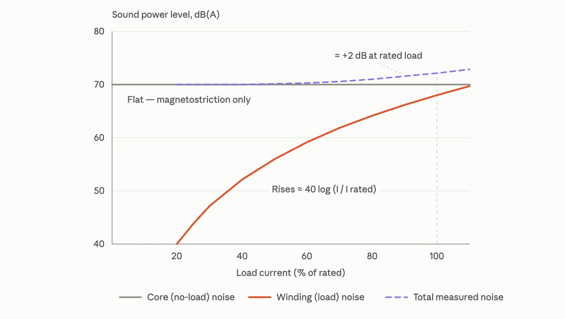
Core noise is present at no load. Winding noise develops as current flows.
Current in the primary and secondary windings produces electromagnetic forces between conductors. These forces vary through the electrical cycle and can cause microscopic movement within the winding assembly. Because electromagnetic force is related approximately to the square of current, winding forces can rise rapidly as loading increases.
A properly designed transformer restrains this movement through conductor geometry, spacers, blocking, bracing and insulation treatment. Under normal conditions, winding vibration remains controlled. The situation changes when the transformer is heavily loaded, mechanically damaged or exposed to a significant short-circuit event.
Short-circuit currents create forces far above normal operating levels. A transformer may remain electrically functional after a fault while experiencing movement within its winding-support system. A new load-dependent buzz following a short circuit deserves investigation even when insulation resistance and routine electrical measurements appear acceptable.
Vacuum pressure impregnation and related resin-treatment processes improve the mechanical integrity of a winding assembly by bonding conductors and insulation into a more rigid structure. They can reduce movement within the windings, but they do not eliminate magnetostriction in the core. The two noise sources must not be treated as the same problem. Our overview of VPI and VPE transformer construction provides more detail on how these insulation processes affect mechanical and dielectric performance.
Harmonics Can Change the Sound, but the Mechanism Matters
Non-linear loads are often blamed whenever a transformer becomes noisy. The connection is real, but it requires qualification.
The main core flux is established primarily by the applied voltage and frequency. Harmonic current drawn by a load does not automatically create an equivalent harmonic component in the main core flux. Current harmonics do, however, increase winding forces and produce stray magnetic flux in conductors, clamps, structural steel and enclosure components. These effects can introduce higher-frequency vibration and additional load noise.
Voltage distortion acts differently. Harmonic components in the applied voltage alter the core-flux waveform directly and can add magnetic excitation at additional frequencies. Whether load-current distortion produces meaningful voltage distortion depends partly on the impedance of the source and distribution system.
This distinction matters during troubleshooting. A current waveform with high total harmonic distortion does not, by itself, prove that the main core is being overexcited. Current, voltage, frequency, loading and sound should be evaluated together.
Where harmonic loading is substantial, the transformer must be designed for the resulting thermal and mechanical duty. A K-factor-rated transformer is designed to tolerate specified harmonic loading without excessive overheating. A harmonic-mitigating transformer uses winding arrangements and phase displacement to reduce selected harmonic currents in the wider system. Neither product should be selected solely as a general-purpose noise-control measure; the choice must be based on the electrical load profile.
Fans, Airflow and Enclosures Add Their Own Sound
Forced-air cooling introduces a separate noise source. Fan sound is generally broader and higher in frequency than core hum, making it easy to distinguish when the fans switch on.
Fan speed, blade design, motor condition and airflow resistance all affect the result. Restricted ventilation openings can produce turbulence, while dust accumulation or damaged bearings can create tonal or irregular noise. A transformer may therefore meet its natural-air sound requirement but become more noticeable when forced cooling operates.
The enclosure also acts as a radiator. Large sheet-metal panels can respond to internal vibration and produce a drum-like effect. Panel stiffness, fastening points, clearances and damping all affect how much sound reaches the room.
Adding acoustic material inside an enclosure is not automatically a safe correction. Any treatment must preserve dielectric clearances, flame-performance requirements and the airflow needed to control transformer temperature. Reducing noise by restricting cooling can create a more serious thermal problem.
Installation Can Amplify an Acceptable Transformer
Factory sound testing and installed room noise are related, but they are not interchangeable.
A factory test evaluates the transformer under defined conditions. The installed transformer becomes part of a much larger mechanical system that includes its base, floor, walls, conduits, bus connections, cable supports and surrounding equipment.
Two transmission paths are involved.
- Airborne sound travels directly from the core, coils, fans and enclosure into the room.
- Structure-borne vibration passes through the transformer base or connected services into the building. A wall, floor slab, ceiling or sheet-metal duct can then radiate that vibration over a larger surface area.
This is the issue that catches many installations. A transformer is placed on isolation pads, but rigid conduits bridge the isolation and carry vibration directly into the structure. In other cases, the pads are too stiff for the equipment weight and provide little meaningful isolation.
Isolation mounts must be selected for the transformer’s mass, centre of gravity, forcing frequency and required static deflection. Spring systems also need adequate lateral stability and restraint. Installing a generic rubber pad without checking these conditions may change the vibration path without materially reducing it.
Room geometry matters as well. Concrete surfaces, low ceilings and small reflective rooms can reinforce certain frequencies. Corners often make low-frequency sound more noticeable. Locating a transformer against a wall shared with an office, meeting room, studio or residential space can create an acoustic problem even when the electrical-room level appears reasonable.
Sound-sensitive applications must therefore be planned as equipment-and-building problems, not transformer-only problems.
A Change in Sound Should Be Investigated Systematically

A stable hum that has remained consistent with voltage, frequency and operating load is normally expected. A meaningful change deserves attention, but sound alone should not be used to diagnose an internal failure.
-
A Sudden Increase in the Existing Hum
When the basic tone remains similar but becomes substantially louder, check supply voltage, system frequency and tap position. Increased volts per hertz can raise core noise without a corresponding increase in load.
Loading, phase balance and fan operation should then be reviewed. Measurements taken before and after the sound change are more useful than a single reading.
-
A New Metallic Rattle or Sharp Buzz
This type of sound often points to a loose enclosure panel, mounting fastener, conduit support or external sheet-metal component. Accessible external hardware should be checked before assuming the noise comes from the core and coil assembly.
Internal clamps and winding supports should only be inspected under the manufacturer’s procedures and appropriate electrical-safety controls.
-
Noise That Appears After a Fault
A new sound following a short circuit, ground fault or protective-device operation may indicate that the winding or its support system experienced mechanical stress. The transformer should be evaluated in relation to the magnitude and duration of the fault rather than returned to service based only on a visual inspection.
-
Hissing, Crackling or Intermittent Snapping
These sounds are not part of normal transformer hum. They may be associated with contamination, tracking, arcing or discharge activity, although the sound by itself cannot identify the exact source.
When irregular noise is accompanied by overheating, smoke, odour, visible discharge or protective-device operation, the transformer should be de-energized and inspected by qualified personnel under the site’s established safety procedure.
Trending temperature, load, voltage, sound and vibration provides a better basis for diagnosis than relying on human memory. These checks can be incorporated into a structured transformer maintenance program.
Noise Control Begins With the Specification
Low sound is easier to engineer before manufacture than to correct after the transformer, conduits and building finishes are installed.
The transformer designer can control core flux density, core-steel grade, joint geometry, clamping, winding bracing, insulation treatment, internal supports, enclosure stiffness and cooling arrangement. These decisions involve trade-offs. A lower core flux density may reduce sound, but it generally requires more core material and can increase transformer dimensions, mass and cost.
The project specification should identify the actual acoustic requirement rather than relying on a general statement such as “low-noise transformer.” At minimum, the schedule should establish:
- The transformer type, kVA rating, voltage class and cooling mode.
- The applicable sound standard and required average sound level.
- Whether a sound level below the standard value is required.
- Whether the requirement applies under natural-air or forced-air operation.
- The proposed room location and adjacent sound-sensitive occupancies.
- Responsibility for vibration isolators, flexible connections and conduit support.
- Any field sound-testing requirement and the measurement conditions.
A special low-sound transformer will not correct an installation that rigidly couples it to the building. Conversely, extensive acoustic treatment may be unnecessary when the actual problem is an incorrect tap position or loose enclosure panel. The source and transmission path must be identified before the remedy is selected.
Which Sound Standard Applies?
The applicable standard depends on the transformer category, voltage class and market.
For general-application dry-type transformers in the United States, NEMA ST 20-2021, Dry Type Transformers for General Applications, is the relevant NEMA publication. The current edition applies to single-phase and polyphase dry-type transformers used to supply power, heating and lighting circuits.
For Canadian dry-type transformer performance, CSA C9:17 (R2022), Dry-Type Transformers, addresses standardized electrical and mechanical features and test procedures. Its current edition specifically notes the alignment of average audible sound levels with current industry practice.
CSA C22.2 No. 47-13 (R2023), Air-Cooled Transformers (Dry Type) serves a different purpose. It is a Canadian Electrical Code, Part II product-safety and conformity standard. Its scope states that performance requirements are addressed by CSA C9 where applicable. The two CSA standards should therefore not be treated as interchangeable.
NEMA TP 80050-2013 (R2024) is the current designation for the publication formerly known as NEMA TR 1. It covers audible sound levels for several transformer categories but excludes dry-type transformers covered by NEMA ST 20. A broad reference to “NEMA TR 1” is therefore not sufficient for a general-purpose dry-type transformer specification.
The exact permitted sound value should be taken from the table that applies to the transformer’s rating, construction and cooling class. A general range such as 55–65 dBA may provide rough context, but it should not be used as the acceptance criterion for every 500–1000 kVA transformer.
Conclusion
Transformer hum begins with magnetostriction in the core, but the sound heard in an operating facility is rarely produced by one mechanism alone. Core flux density determines the basic no-load excitation. Winding current adds load-dependent mechanical forces. Harmonics can introduce higher-frequency winding and stray-flux effects. Fans, enclosure panels, mounting hardware and the building structure determine how those vibrations reach occupied spaces.
The practical distinction is between sound generation and sound transmission. Core design, winding construction and cooling selection control what the transformer produces. Mounting, flexible connections, conduit support and room acoustics control how strongly the installation reproduces it.
A low-sound requirement should therefore be specified with the applicable standard, operating mode and installation conditions defined. When an existing transformer changes sound, voltage, frequency, loading and external mechanical paths should be checked before the noise is treated as evidence of an internal defect.
Line Reactors vs. Transient Filters: Understanding Their Roles in VFD Systems
Variable Frequency Drives (VFDs) have become an essential part of modern power and motor control systems. They provide precise speed regulation, improve process efficiency, and significantly reduce energy consumption across industrial and commercial facilities. However, the same pulse-width modulation (PWM) technology that enables VFD efficiency also introduces power quality challenges—most notably current harmonics, voltage transients, and high-frequency switching noise.
To mitigate these effects and ensure compliance with harmonic standards such as IEEE 519, electrical systems commonly employ line reactors and transient filters. Both are passive, highly reliable components designed to improve current waveform quality, protect equipment, and extend the life of connected motors and drives. While they share similarities, each serves a distinct function and offers unique performance characteristics.

Harmonics and Transients in VFD Systems
A VFD operates by first rectifying incoming AC voltage into DC, then converting that DC back into a variable-frequency AC signal for motor control. This conversion process is inherently non-linear and introduces two main power quality issues:
Line-side harmonics: The rectifier stage draws current in pulses, creating distortion in the supply current waveform. These harmonics increase transformer losses and may cause upstream voltage distortion.
Load-side transients: The inverter stage generates steep voltage transitions (high dv/dt) that stress motor insulation and may produce reflected wave overvoltages on long motor leads.
Together, these phenomena reduce efficiency, generate excessive heat, and may lead to premature failure of motors, drives, and upstream equipment. Passive mitigation components such as line reactors and transient filters help address these problems by controlling current and voltage distortion at their source.
Line Reactors: Function and Applications
A line reactor is an inductive device designed to add controlled impedance into a circuit, limiting the rate of current change and smoothing waveform distortion. In VFD systems, reactors can be placed on either the line side (input) or the load side (output).
Line-Side Reactors (Input Reactors)
Installed between the power source and the VFD, line-side reactors:
- Reduce current harmonics typically by 30–40%.
- Protect the VFD from upstream voltage spikes and transients.
- Limit inrush current and reduce nuisance overcurrent tripping.
- Improve overall current balance and extend equipment life.
A typical line-side reactor provides 3% or 5% impedance relative to system voltage, which offers an effective balance between harmonic attenuation and voltage drop.
Load-Side Reactors (Output Reactors)
Installed between the VFD and motor, load-side reactors:
- Limit dv/dt (rate of voltage rise) from the VFD inverter output.
- Reduce reflected wave voltage on long cable runs.
- Decrease motor insulation stress and extend motor life.
- Minimize audible noise and heating in motor windings.
Load-side reactors are especially recommended for systems where motor lead lengths exceed 15 to 30 metres (50 to 100 feet).
Transient Filters: Function and Benefits
A transient filter combines resistive (R) and inductive (L) elements in a single passive network. This configuration attenuates harmonic currents more effectively than a standalone reactor while preventing the resonance issues that can occur in purely inductive or capacitive filtering systems.
Construction and Operation
Inductors oppose rapid changes in current, reducing the amplitude of harmonic components.
Resistors provide damping, dissipating residual harmonic energy and stabilizing system response.
Together, they create a balanced impedance path that smooths current flow and minimizes harmonic propagation without relying on capacitors.
Applications
R–L filters are typically installed on the input side of the VFD to:
Improve current waveform and lower total harmonic distortion (THD).
Support compliance with IEEE 519 harmonic limits at the point of common coupling (PCC).
Reduce transformer and cable heating caused by harmonic currents.
Prevent resonance between VFDs and other system components.
Advantages
Effective harmonic reduction, often lowering current THD to 8–10% under typical load conditions.
No capacitors, thus eliminating the risk of resonance with system capacitance.
Minimal maintenance and long operating life due to simple, robust construction.
Compact footprint relative to complex harmonic filter assemblies.
Comparing Line Reactors and Transient Filters

Selection Guidelines

Selecting the appropriate device depends on system characteristics, harmonic objectives, and cost considerations.
For general installations:
A 3% input line reactor is typically sufficient to limit transients and moderately reduce harmonic current distortion.
For systems with multiple VFDs or tighter harmonic targets:
An R–L filter provides deeper harmonic attenuation and damping, improving compliance with IEEE 519 limits.
For long motor leads or high dv/dt applications:
A load-side reactor remains the preferred solution to protect motor insulation.
Confirm system performance:
Always verify harmonic levels at the PCC relative to the system short-circuit ratio (Isc/IL) and design with margin for future load expansion.
Benefits of Proper Application
When correctly specified and installed, line reactors and R–L filters deliver significant benefits:
- Improved VFD and motor reliability.
- Reduced nuisance trips and voltage stress.
- Compliance with IEEE 519 harmonic limits.
- Reduced heating in transformers, cables, and conductors.
- Lower overall system losses and improved power factor.
- Enhanced operational safety and uptime.
Conclusion and Industry Perspective
Line reactors and R–L filters are essential tools for managing harmonics and transients in variable frequency drive systems. Both are simple, proven, and maintenance-free solutions that improve waveform quality and safeguard critical equipment. Line reactors offer an economical choice for general protection, while R–L filters deliver enhanced harmonic reduction and resonance control for more demanding applications.