Updated: August 17th, 2026
A variable frequency drive can show high current total harmonic distortion at its input while the facility still meets Institute of Electrical and Electronics Engineers Standard 519 (IEEE 519). The reverse can also happen: a moderate current-distortion reading may produce unacceptable voltage distortion when the source is weak or a capacitor bank creates resonance.
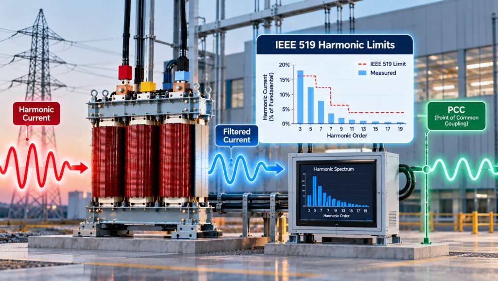
The missing detail is the measurement point. IEEE 519 does not impose one total harmonic distortion limit on every drive, panel, transformer, or electronic load. It establishes steady-state voltage and current distortion goals at the user point of common coupling (PCC). The PCC, system short-circuit strength, demand load current, harmonic spectrum, and operating condition all affect the assessment.
This article explains what the measurements mean, how the principal IEEE 519 limits are applied, and what those limits imply for transformer and harmonic-mitigation design.

What Harmonic Current Does to the Electrical System
Harmonics are voltage or current components at integer multiples of the fundamental frequency. On a 60 Hz system, the third harmonic is 180 Hz, the fifth is 300 Hz, and the seventh is 420 Hz.
They are produced mainly by non-linear loads. A rectifier, switch-mode power supply, variable frequency drive, uninterruptible power supply, LED driver, or electric vehicle charger draws current in pulses rather than as a smooth sine wave. Those pulses contain harmonic components that flow through transformers, bus bars, cables, and the source impedance.
The load produces harmonic current. When that current flows through supply-system impedance, it creates harmonic voltage drop. A stronger system generally experiences less voltage distortion for the same injected harmonic current; a weaker system experiences more.
Higher-frequency components also increase winding eddy-current and stray losses in transformers. In four-wire systems, triplen harmonics such as the third, ninth, and fifteenth are zero-sequence components. They can add in the neutral instead of cancelling, creating substantial neutral current even when the three-phase fundamental load appears balanced. Transformer connections and winding arrangements therefore affect how these currents circulate and where their effects appear. The practical differences between common connections are discussed further in our article on wye vs. delta, discussing connection choices and what they mean in practice.
For more detail on harmonic heating, see our guide to understanding the k-factor of transformers and harmonics and to understanding losses in transformers.
Why the Point of Common Coupling Controls the Assessment
Measurements taken at the input of a drive or uninterruptible power supply describe that equipment and its local circuit. They do not, by themselves, establish IEEE 519 performance.
The correct PCC must be established from the system arrangement, utility requirements, and project documents before data is interpreted. In a simple service, it may be close to the service entrance. In a campus, industrial plant, or distributed-energy installation, the applicable interface may require more careful definition.
A high current total harmonic distortion value at a lightly loaded branch circuit can look severe while the total harmonic current at the PCC remains acceptable. Conversely, several individually acceptable loads can combine at the PCC and exceed an individual harmonic or total demand distortion limit.
IEEE confirms that its steady-state voltage and current distortion limits apply at the user PCC for facilities containing harmonic-producing loads.
THD, TDD, and Individual Harmonics Are Not Interchangeable

Total harmonic distortion (THD) compares the root-sum-square harmonic content with the fundamental component of the waveform. Voltage THD is commonly written as THD-V, while current THD may be written as THD-I.
Current THD can be misleading at light load. If the harmonic current remains present while the fundamental current falls, the percentage rises because the denominator is smaller. A high instantaneous current THD reading therefore does not automatically indicate a high harmonic contribution relative to the facility’s demand.
Total demand distortion (TDD) uses the maximum demand load current, IL, as the reference instead of the instantaneous fundamental current. This creates a more stable basis for current limits at the PCC. IL is not simply the transformer nameplate current or whatever current happens to be measured during a short site visit. The load basis should reflect the project’s demand calculation and operating profile.
Individual harmonic distortion (IHD) evaluates each harmonic order separately. A system can remain within its total TDD limit and still exceed the limit for the fifth, seventh, eleventh, or another individual harmonic. The spectrum must therefore be reviewed, not just the total value.
K-Factor is different again. It represents the transformer heating effect of a harmonic current spectrum. It helps determine whether a transformer is thermally suitable for the load, but it is not an IEEE 519 compliance measurement.
IEEE 519 Voltage Distortion Limits
IEEE 519-2022 is the active edition and supersedes IEEE 519-2014. Its steady-state limits apply at the user PCC; they are not universal limits for equipment terminals.
For the voltage classes most commonly encountered in low- and medium-voltage facilities, the principal limits are:
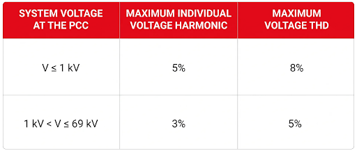
Tighter limits apply above 69 kV. The separate category for systems at or below 1 kV is important because it differs from the older practice of applying the 5% THD figure broadly to all systems below 69 kV.
An internal bus near a heavily distorted load may show a different value. Whether that value is acceptable depends on equipment capability and project criteria, even when the PCC remains within IEEE 519.
IEEE 519 Current Distortion Limits
Current limits depend partly on the ratio of available short-circuit current at the PCC, Isc, to maximum demand load current, IL. The ratio indicates system strength at that location.
A high Isc/IL ratio means the source is relatively stiff compared with the load. More harmonic current can flow before it produces the same voltage distortion. A low ratio indicates a weaker source, so the allowable current distortion is lower.
For systems from 120 V through 69 kV, the maximum TDD values are:
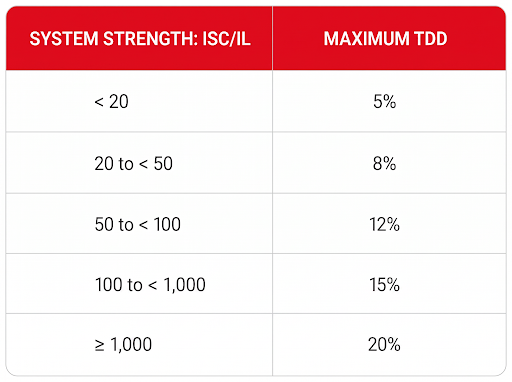
This is only the maximum TDD column. IEEE 519 also establishes limits for individual current harmonics according to harmonic order and system conditions. A complete study cannot use the table as a stand-alone pass-or-fail check.
Available short-circuit current must correspond to the applicable system condition and PCC. Transformer impedance, upstream source impedance, and system configuration affect the result. Explore our guides to transformer fault-current calculation and impedance in transformers for the underlying relationships.
How IEEE 519 Applies in Canadian Projects
IEEE 519 is widely used in Canadian power-quality studies, specifications, and utility interconnection requirements. It should not be described as a law that automatically applies to every installation.
CSA C22.1:24 is the 26th edition of the Canadian Electrical Code, Part I, an electrical-installation safety standard. Provinces and territories determine which edition and amendments have legal effect. IEEE 519 becomes a project requirement when it is incorporated through utility rules, connection agreements, engineering specifications, contracts, owner criteria, or requirements imposed by the authority having jurisdiction.
Hydro One’s March 2026 distributed-energy interconnection requirements provide one current example. The document applies harmonic requirements at the PCC and refers to IEEE 519 when an installation contains primarily harmonic-producing loads or a mixture of loads and inverter-based resources. That is a specific interconnection requirement, not a universal rule for every Canadian facility.
Before stating that a system complies with IEEE 519, confirm the governing document, PCC, measurement method, operating period, voltage class, short-circuit data, and acceptance limits.
Selecting the Correct Harmonic-Control Response
A harmonic solution should follow the measured problem. Selecting a K-Factor transformer, reactor, or filter from a single THD number can solve the wrong issue.
Establish Representative Operating Conditions
The study should capture voltage THD, current THD, TDD, individual harmonic magnitudes, demand loading, neutral current, transformer loading, available short-circuit current, and existing capacitor banks.
Trend data is usually more useful than one snapshot because drives, chargers, uninterruptible power supplies, and production equipment may operate differently by shift or process state. Measurements should represent the conditions under which the system is expected to meet its distortion targets.
Reduce Harmonic Current Near the Source
Line reactors, direct-current-link chokes, multi-pulse rectifiers, low-harmonic drives, active-front-end converters, and equipment with built-in correction can reduce current injected by individual loads. Their performance is load-dependent. A reactor that improves the current waveform of a six-pulse drive does not guarantee a particular TDD value at the PCC.
Where deeper attenuation is required, passive or active filters may be appropriate. Passive filters must be selected against the actual spectrum and system impedance. Their behaviour can change after a transformer replacement, capacitor-bank addition, or utility configuration change.
Explore line reactors vs. transient filters and passive harmonic filters for the differences between these devices.
Check Capacitor Banks for Resonance
Power-factor-correction capacitors and system inductance form a resonant circuit. If the resonant frequency lies near a dominant harmonic order, voltage and current can be amplified rather than reduced.
The result may be capacitor fuse operation, overheating, nuisance trips, or unexpectedly high voltage distortion. Capacitor banks should therefore be included in the harmonic model. Detuned banks, series reactors, filters, or a different compensation arrangement may be required.
Match the Transformer to the Objective
A K-Factor rated transformer is designed to carry a specified harmonic-rich load without exceeding its thermal limits. It addresses the consequence of harmonic current inside the transformer. It does not automatically reduce upstream harmonic current or establish IEEE 519 compliance.
A harmonic-mitigating transformer is intended to reduce selected harmonic components through engineered winding configurations, phase shifting, and, where applicable, zero-sequence harmonic treatment. Its performance depends on load balance, harmonic spectrum, transformer grouping, and phase-shift arrangement.
The two transformer types solve different problems. One manages the additional thermal duty. The other is intended to change the harmonic current presented to the upstream system.
Verify the Installed System
Repeat measurements should be taken at the same defined locations and under comparable operating conditions.
Verification should confirm the applicable voltage THD, TDD, and individual harmonic limits. It should also confirm neutral current, conductor loading, power factor, and transformer temperature. Acceptable PCC readings do not eliminate the need to verify that the transformer and connected conductors remain within their thermal ratings.
Conclusion
IEEE 519 is not a single THD limit, and it is not a transformer rating. It is a system-level framework for controlling steady-state voltage and current distortion at the user PCC.
The engineering decision begins with the correct measurement point and representative operating data. The voltage class, Isc/IL ratio, individual harmonic spectrum, system impedance, transformer loading, neutral current, and capacitor-bank interaction must then be considered together.
A K-Factor transformer can tolerate additional harmonic heating. A harmonic-mitigating transformer, reactor, or filter may reduce selected harmonic currents. None should be specified from a single instrument percentage. The equipment should be selected against the load spectrum, system strength, PCC target, and operating conditions the installation will actually see.