Updated: August 17th, 2026
Transformer load calculation is often presented as a simple exercise: add the connected equipment, apply a percentage margin, and select the next standard kVA rating. That approach can produce a number, but it does not necessarily produce the right transformer.
A transformer has to carry the maximum coincident load without exceeding its thermal limits. It may also have to start motors without an unacceptable voltage dip, supply nonlinear loads without excessive additional heating, and operate in ambient and ventilation conditions that differ from the assumptions behind its nameplate rating. These requirements are related, but they are not captured by one universal multiplier.
A useful load calculation therefore moves through three stages. First, establish the connected load on a consistent kVA basis. Next, determine the credible maximum demand using the applicable electrical code, operating sequence, and available measurements. Finally, check the electrical, thermal, and environmental conditions that can change the transformer selection.
This guide focuses on that complete process. For a narrower explanation of the single-phase and three-phase equations, see Rex Power Magnetics’ guide to calculating kVA for transformer sizing.
 What a Transformer Load Calculation Must Establish
The connected load is the sum of all equipment that could be supplied by the transformer. Maximum demand is the greatest coincident load expected during the relevant operating period. The selected transformer rating must support that demand under the specified service conditions, with any required provision for load growth and transient duty.
Those values are not automatically the same. A facility may have several machines that are physically connected but prevented by controls from operating together. A commercial building may have lighting, receptacle, heating, cooling, and charging loads whose peaks occur at different times. Conversely, a process line may operate nearly all of its connected equipment continuously, leaving little difference between connected load and maximum demand.
The calculation must reflect the actual system. Applying an assumed percentage to the total connected load without a code basis, operating sequence, or measured profile can undersize the transformer just as easily as it can prevent oversizing.
Why Transformer Load Is Calculated in kVA
Transformers are rated in kilovolt-amperes (kVA), not kilowatts (kW), because their windings must carry current regardless of how much of the apparent power becomes useful real power at the load. A 50 kW load operating at a power factor of 0.80 requires 62.5 kVA from the transformer. Treating that load as 50 kVA would understate winding current by 20%.
For a single-phase load:
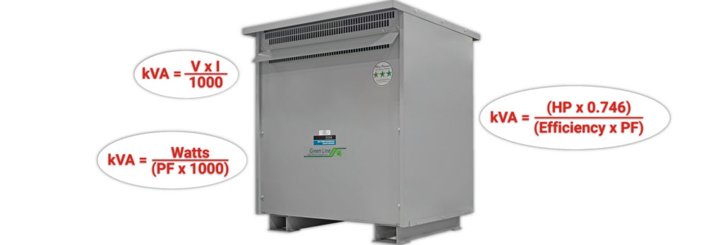
kVA = (V × I) ÷ 1,000
For a balanced three-phase load:
kVA = (√3 × VLL × IL) ÷ 1,000
Where:
VLL = line-to-line voltage
IL = line current in amperes
Using line-to-neutral voltage in the three-phase equation understates the load by a factor of √3.
When real power and power factor are known:
kVA = kW ÷ power factor
For a motor rated in horsepower:
Motor input kVA = (HP × 0.746) ÷ (efficiency × power factor)
Horsepower represents mechanical output, so both efficiency and power factor are required to estimate electrical input. If reliable motor nameplate current or manufacturer input data is available, calculating kVA from voltage and current is normally preferable to assuming typical efficiency and power-factor values.
These equations convert known load data into a common unit. Rex’s transformer calculators can perform the kVA, kW-to-kVA, and horsepower-to-kVA conversions, but the calculator cannot determine which loads will operate together or whether the resulting load profile is suitable for a particular transformer.
Building the Load Schedule
A defensible transformer selection begins with a load schedule that records what is connected, how it operates, and which source data supports the calculation.

Identify Every Connected Load
The schedule should include lighting, receptacles, heating, ventilation and air-conditioning equipment, motors, drives, uninterruptible power supplies, battery chargers, process heaters, welding equipment, control power, and planned additions. For each item, record the supply voltage, phase, full-load current or input kW, power factor where applicable, efficiency where mechanical output is given, quantity, and duty cycle.
Input data matters. A 40 W lamp rating does not necessarily represent the complete input of its driver or ballast. A motor’s horsepower rating describes shaft output rather than transformer input. A variable-frequency drive should be evaluated from its electrical input and operating duty, not simply from the motor horsepower connected to its output. Manufacturer data should be used where available.
Existing installations provide another source of evidence. Interval metering, power-quality monitoring, and supervisory control and data acquisition records can show the actual peak kVA, phase balance, power factor, harmonic current, and duration of loading. A short spot measurement may miss seasonal or production peaks, so the monitoring period has to represent the operating cycle being evaluated.
Convert the Loads to a Common kVA Basis
Each load should be converted to input kVA before it is added to the schedule. Resistive heaters may operate close to unity power factor, but electronic lighting, drives, rectifiers, and uninterruptible power supplies may not. “Capacitive load” does not require a different apparent-power formula; voltage and RMS current still determine VA. What changes is the current phase relationship and, for nonlinear equipment, the waveform.
Three-phase totals should also be checked by phase. A transformer may be within its total three-phase kVA rating while one phase or the neutral is overloaded by unevenly distributed single-phase loads. The load schedule should therefore show phase allocation rather than only one combined total.
Establish Maximum Coincident Demand
Connected load should be reduced only where the applicable electrical code or a defensible operating basis permits it. In Canada, the adopted edition of the Canadian Electrical Code, Part I and provincial or territorial amendments govern the installation. Project requirements may differ by jurisdiction, occupancy, load type, and authority having jurisdiction.
Demand factor and diversity factor should not be used interchangeably:
Demand factor = maximum demand ÷ total connected load
Demand factor is normally no greater than 1 because maximum demand does not exceed the connected load to which it is being compared.
Diversity factor = sum of individual maximum demands ÷ maximum coincident demand
Diversity factor is generally 1 or greater because individual load peaks may occur at different times. Coincidence factor, the reciprocal concept, is normally no greater than 1.
This terminology matters. Multiplying the connected load by an unsupported “diversity factor” of 0.7 may appear conservative, but it is actually applying a coincidence or demand assumption. The assumption needs a code rule, interlocked operating sequence, historical profile, or other documented basis.
Account for Duty Cycle and Load Duration
Two loads with the same peak kVA can impose different thermal duties. A process that remains near maximum demand for every production shift heats the transformer differently from an intermittent machine that runs for a few minutes each hour. Cyclic loading may permit thermal behaviour that a simple steady-state total does not describe, but any loading above the nameplate rating requires an application-specific thermal assessment rather than an assumed overload allowance.
The transformer nameplate rating represents continuous capability under defined conditions. Rex’s transformer rating guide explains how rated kVA is connected to voltage, current, temperature rise, insulation system, cooling, and service environment.
Check Motor Starting and Other Transient Loads
Motor running kVA establishes the steady-state contribution. Motor starting is a separate check. Across-the-line starting can draw several times the running current, and the resulting current through the source, transformer, and conductor impedance produces a temporary voltage drop.
The correct assessment uses the motor’s locked-rotor current or code information, starting method, acceleration time, number of motors already running, transformer impedance, upstream source strength, and allowable voltage dip at the motor and other connected equipment. The full starting kVA is not normally added to the continuous load as though it were permanent. Instead, it is evaluated as a transient duty and voltage-performance problem.
Transformer energization inrush is different again. It is created by core flux during energization and affects protection coordination and source disturbance, but it is not part of the downstream operating-load total. Rex’s guide to transformer inrush current explains why switching angle, residual flux, core design, and source impedance influence this event.
Evaluate Nonlinear Loads Separately
Variable-frequency drives, uninterruptible power supplies, rectifiers, LED drivers, computers, and other power-electronic loads draw nonsinusoidal current. Their true RMS current contributes to winding heating, while harmonic components increase eddy-current and other stray losses. Triplen harmonics from single-phase nonlinear loads can also add in the neutral of a three-phase four-wire system.
A correct fundamental-frequency kVA calculation can therefore still select the wrong transformer construction. The harmonic spectrum, current total harmonic distortion, neutral loading, and load mix may require a K-factor-rated or harmonic-mitigating design rather than simply a larger general-purpose unit. IEEE C57.110-2018 provides methods for evaluating transformer capability when supplying nonsinusoidal load currents. Rex’s guide to K-factor transformers and harmonics explains how harmonic load characteristics affect selection.
Check Ambient, Altitude, Enclosure, and Cooling
The calculated kVA assumes the transformer can reject the heat produced by its core, winding, and stray losses. Elevated ambient temperature reduces the temperature margin between the windings and their allowable limit. High altitude reduces air density and cooling effectiveness. Restricted clearances, blocked ventilation openings, dust accumulation, solar loading, and an enclosure selected for a difficult environment can also change thermal performance.
These conditions should be given to the manufacturer rather than addressed through a generic percentage margin. Rex’s guide to thermal management in dry-type transformers explains how cooling method, insulation class, temperature rise, airflow, ambient conditions, and monitoring work together.
Add Future Capacity Deliberately
Future growth is a project requirement, not a universal 25% rule. A fixed process with a known production limit may need little spare capacity. A tenant building, phased industrial expansion, data centre, or electrification project may justify substantially more. The allowance should be tied to identified future loads, timing, available space, upstream capacity, and the cost of later replacement.
Excessive oversizing also has consequences. A larger transformer costs more, occupies more space, may increase available fault current, and carries no-load losses whenever it is energized. Since load losses rise approximately with the square of load current while no-load losses remain present regardless of output, the expected operating profile should be considered alongside initial kVA. Rex’s guide to transformer losses explains this relationship.
Worked Transformer Load Calculation
Consider a small three-phase facility supplied by one transformer. The connected load consists of fifty lighting fixtures with 40 W input each at 0.95 power factor and three 5 hp motors. Each motor operates at 85% efficiency and 0.80 power factor.
The lighting load is:
Lighting kVA = 2.0 kW ÷ 0.95 = 2.11 kVA
The running load of each motor is:
Motor kVA = (5 × 0.746) ÷ (0.85 × 0.80) = 5.49 kVA
The total connected running load is therefore:
Connected load = 2.11 + (3 × 5.49) = 18.58 kVA
Suppose the documented control sequence permits only two motors to run simultaneously, while the complete lighting load may be on. The calculated maximum steady-state operating load becomes:
Maximum operating load = 2.11 + (2 × 5.49) = 13.09 kVA
If the project also identifies 4 kVA of future coincident load, the design load becomes:
Design load = 13.09 + 4.00 = 17.09 kVA
On continuous kVA alone, a 25 kVA transformer becomes a reasonable candidate. It is not yet a complete selection. If one motor starts while the other two and the lighting remain in service, the transient current may produce an unacceptable voltage dip even though the normal operating load is well below 25 kVA. The motor-starting method, locked-rotor current, transformer impedance, source impedance, conductor voltage drop, acceleration time, and sensitivity of the other loads must still be checked.
The example demonstrates why the old shortcut of multiplying connected load by 0.7 and then by 1.25 is not a sound substitute for an operating analysis. The two arbitrary factors can partly cancel each other while hiding the information that actually determines whether the system will work.
What Transformer Calculator Tools Can and Cannot Do
A calculator is useful for converting volts and amperes to kVA, converting kW at a stated power factor, or estimating motor input from horsepower, efficiency, and power factor. It also reduces arithmetic and unit-conversion errors when several scenarios have to be checked.
It cannot know whether the source data represents input or output power, whether loads are balanced, which equipment operates simultaneously, whether a demand factor is permitted, or whether a short-duration load creates an unacceptable voltage dip. It also cannot infer the harmonic spectrum, ambient conditions, altitude, enclosure restrictions, available fault current, or future expansion plan unless those conditions are explicitly modelled.
Calculator output should therefore be treated as one part of the load schedule, not as approval of the final transformer. The calculated rating should be checked against the transformer’s voltage, phase, frequency, winding connection, taps, impedance, temperature rise, insulation class, enclosure, cooling method, and applicable standards. Rex’s transformer nameplate guide explains where the finished transformer’s principal ratings and connection information are recorded.
Common Transformer Load Calculation Errors
The most common error is mixing kW and kVA. Power factor must be applied when real power is converted to apparent power, but it should not be applied a second time when voltage and RMS current already define kVA.
Another error is adding output ratings rather than electrical input. Motor horsepower, delivered uninterruptible-power-supply output, lamp wattage, and drive output do not necessarily equal the kVA drawn from the transformer. Efficiency, power factor, auxiliaries, and operating point all matter.
Demand assumptions also cause significant errors. Loads should not be removed from the maximum-demand calculation simply because they “usually” do not run together. The operating restriction must be established through code-permitted demand factors, interlocks, process logic, or representative measurements.
Starting current is often handled incorrectly in one of two ways. Ignoring it can lead to failed motor acceleration, contactor dropout, dimming, or nuisance operation of protective devices. Adding it to continuous kVA as though it never decays can lead to unnecessary oversizing. It needs a transient check.
Finally, a correct kVA total can still be incomplete. Phase imbalance, nonlinear current, neutral loading, ambient temperature, altitude, restricted ventilation, voltage regulation, short-circuit duty, and protection coordination can all affect the equipment specification after the arithmetic is finished.
Information Required for Final Transformer Selection
Before a calculated load becomes a purchase specification, the primary and secondary voltage, phase, frequency, and winding connection should be confirmed. The connected load schedule and maximum coincident demand should also be reviewed, along with the continuous, intermittent, cyclic, and transient duties the transformer will serve.
Loads that create unusual electrical demands require additional attention. For motor loads, confirm the starting method, starting current, and permissible voltage dip. For nonlinear loads, assess the expected percentage of nonlinear loading, harmonic spectrum, and neutral current. Planned equipment additions should also be considered so the transformer includes an appropriate expansion allowance without being unnecessarily oversized.
The installation conditions are equally important. Confirm the ambient-temperature range, altitude, ventilation, and enclosure requirements, as these factors affect cooling and usable capacity. Required impedance, voltage regulation, and available fault-current limits must also be established so the transformer performs correctly within the wider electrical system.
Finally, review the protection, grounding, bonding, and applicable electrical-code requirements. The purchase specification should identify the relevant CSA, UL, IEEE, NEMA, efficiency, and project-specific standards by their exact document numbers and required editions.
NEMA’s dry-type transformer purchasing specification guide provides a useful reference for many of the electrical, environmental, construction, testing, and documentation details that have to be defined after the load is established.
Conclusion
Transformer load calculation is not simply connected kVA plus a safety percentage. The calculation has to distinguish connected load from maximum coincident demand, use correct electrical input data, and account for duty cycle, motor starting, nonlinear current, environmental conditions, and planned growth.
The arithmetic identifies a candidate kVA rating. The surrounding system determines whether that candidate will operate reliably. A transformer that is adequate thermally may still produce an unacceptable voltage dip during starting, while a transformer that carries the fundamental-frequency kVA may still overheat under harmonic current. Conversely, unnecessary spare capacity can increase capital cost and no-load losses without solving a defined application problem.
For new or complex installations, involve Rex Power Magnetics early in the selection process. Share the load schedule, operating sequence, source characteristics, harmonic profile, environmental conditions, and anticipated future growth. Our engineering team can use this information to select and design a transformer for the system’s actual operating duty, rather than relying on a generic capacity percentage that may not reflect the application.