Updated: August 17th, 2026
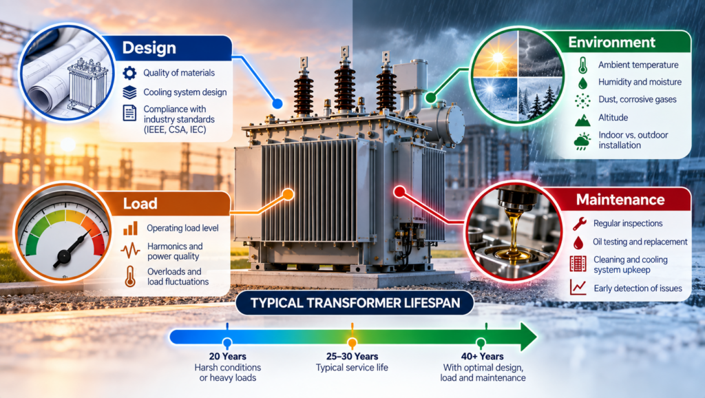
A transformer does not reach the end of its useful life simply because it passes a particular number of years in service. Some units operate reliably for decades, while others develop insulation or thermal problems much earlier. The difference is usually found in the relationship between design, temperature, load duty, environment, and maintenance.
For dry-type transformers, the insulation system is central to service life. Heat gradually changes the electrical and mechanical properties of insulation, but average load alone does not reveal the complete thermal duty. Harmonic current, blocked airflow, high ambient temperature, phase imbalance, repeated overloads, and poor connections can create hot spots even when the apparent load seems acceptable.
Transformer lifespan is therefore an asset-condition question, not a fixed calendar estimate. Understanding what has stressed the transformer, and for how long, gives teams a stronger basis for selection, maintenance, and replacement planning.
Transformer Age is Not the Same as Transformer Condition
Published life ranges can be useful for high-level asset planning, but they should not be treated as an expiry date. Chronological age records the time since manufacture or energization. Condition reflects what has happened to the transformer during that time.
A lightly loaded transformer in a clean, well-ventilated electrical room may retain substantial service capability after many years. A newer unit can age more rapidly if it operates near a heat source, repeatedly carries harmonic-rich current, experiences moisture or contamination, or has ventilation openings obstructed by dust or stored material.
The important concept is consumed insulation life. IEC 60076-12, the loading guide for dry-type power transformers, provides a method for estimating ageing rate and life consumption as functions of operating temperature, time, and loading. This does not produce an exact failure date. It provides a thermal model that becomes more useful when it is supported by reliable load and temperature history.
A credible remaining-life assessment combines operating history with inspection, testing, and knowledge of the application. It also considers terminations, supports, cooling equipment, controls, and contamination rather than insulation alone.
Why Temperature Drives Insulation Ageing
A transformer’s kVA rating is fundamentally a thermal limit. Core losses are present whenever the transformer is energized, while winding and stray losses increase with load current. The resulting heat must move from the conductor through the insulation and winding structure to the surrounding air.
The most highly stressed location is the winding hot spot, not necessarily the point measured by an enclosure sensor or an infrared scan. Rex’s transformer rating guide explains how rated kVA, current, temperature rise, insulation class, cooling, and service conditions work together.
Insulation class and temperature rise must also be distinguished. The insulation class identifies the thermal capability of the insulation system. The specified winding temperature rise describes how much the average winding temperature may increase above the reference ambient under rated conditions. A higher insulation class does not make every operating temperature equally desirable, and temperature margin is not a general-purpose overload allowance.
Winding geometry, conductor arrangement, cooling ducts, losses, and enclosure ventilation all influence hot-spot temperature. Good design limits localized heating instead of relying only on an acceptable average. Rex’s article on thermal management in dry-type transformers examines how airflow and insulation design control this process.
Design Determines How Stress Is Managed
Long service life begins with a transformer designed for the actual duty. Copper and aluminum windings can both provide reliable service when conductor area, joints, bracing, insulation, and cooling are engineered correctly. Conductor material alone does not determine longevity.
Winding construction affects both heat transfer and short-circuit strength. Conductor dimensions, layer or disc arrangement, insulation thickness, cooling channels, clamping, and bracing influence how the winding responds to continuous load, starting current, and fault forces. Rex’s guide to transformer winding design explains why electrical, thermal, and mechanical requirements cannot be separated.
Core design also matters. Flux density and core-joint construction affect excitation current, no-load loss, temperature, and sound. Operation at excessive volts per hertz can push the core closer to saturation, increasing magnetizing current and heating. This may occur because of overvoltage, underfrequency, incorrect taps, or an application that does not match the nameplate frequency.
Enclosure and cooling design must suit the installation. A ventilated transformer relies on clean air passages and adequate clearance. Encapsulated or cast-coil construction may better resist particular contaminants or moisture conditions, but no construction solves every environmental problem.
Load Profile Matters More Than One Current Reading
Continuous overload increases winding temperature, but duty cannot be judged from one spot measurement. Load duration, cycles, starting events, phase balance, ambient temperature, and cooling equipment all affect the result.
Repeated heating and cooling can also impose mechanical stress. Conductors, insulation, terminals, and supports expand and contract at different rates. A transformer designed for cyclic duty can manage these changes, but severe or frequent temperature swings can contribute to loosened connections and insulation deterioration over time.
Motor starting, transformer energization, welding loads, and other short-duration events require separate consideration. They may not add much to average thermal load, but they can cause voltage drop and electromechanical force. A fault is more severe: short-circuit current produces forces that rise approximately with the square of current. Even when protective devices clear the event, winding bracing and connections may have been stressed.
Proper transformer sizing and selection require more than rounding a load calculation to the next standard kVA. The design must reflect coincident demand, duty cycle, inrush, motor starting, growth, source conditions, and the cooling environment.
Harmonic Loads Can Consume Thermal Margin
Variable-frequency drives, uninterruptible power supplies, rectifiers, LED drivers, computers, battery chargers, and other power-electronic loads draw nonsinusoidal current. A transformer can be within its nameplate kVA and still experience greater-than-expected heating if the design does not account for the harmonic spectrum.
Harmonic current increases winding eddy-current and other stray losses. Triplen harmonics from single-phase nonlinear loads can add in a three-phase four-wire neutral, while phase imbalance can place greater thermal duty on one winding.
IEEE C57.110-2018 provides methods for evaluating transformer capability when supplying nonsinusoidal load currents and information for specifying new transformers for such loads. Depending on the measured or predicted spectrum, the correct response may be a K-factor-rated transformer, a harmonic-mitigating transformer, revised winding construction, or another system-level measure. A K-factor rating indicates an ability to withstand defined harmonic heating; it does not filter harmonics. Rex’s guide to K-factor transformers and harmonics explains this distinction.
Environment Can Change the Available Thermal Capacity

Nameplate capability is based on defined service conditions. When the actual installation departs from those conditions, the transformer may have less thermal margin than the load calculation suggests.
High ambient temperature reduces the margin available for heat rejection. At high altitude, lower air density reduces air-cooling effectiveness. Restricted clearances, recirculated exhaust, failed fans, or blocked ducts similarly prevent heat from leaving as intended.
Dust can settle on windings and in cooling passages, restricting airflow and creating insulating layers that retain heat. Conductive or chemically aggressive contamination introduces additional risks, including tracking, corrosion, and deterioration of exposed insulation surfaces. Moisture can reduce insulation resistance and support surface discharge, particularly where contaminants are already present.
Enclosure selection must address the actual hazard. Outdoor exposure, wind-driven rain, salt, chemicals, and combustible dust require different decisions. A more restrictive enclosure may affect ventilation, so cooling and certification requirements must be reviewed with it.
Mechanical environment matters as well. Persistent vibration from nearby machinery, poor mounting, transport damage, or seismic events can affect core clamps, bracing, terminals, and connections. The transformer should be installed on a suitable foundation and isolated from external vibration where the application requires it.
Maintenance Preserves the Conditions Assumed by the Design
Maintenance does not reverse insulation ageing, but it can prevent avoidable stresses from accelerating it. Inspection and cleaning preserve airflow. Connection checks help identify looseness or oxidation before high resistance creates a hot spot. Load and temperature records show whether the transformer is operating within the duty used for selection.
Thermography can reveal abnormal heating while equipment carries representative load. Insulation-resistance, winding-resistance, and turns-ratio testing may add evidence when compared with baseline or historical results. Trends and corroborating evidence are more useful than isolated values.
Diagnostic methods must also match the transformer type. Dissolved gas analysis is valuable for liquid-filled transformers because gases generated by thermal and electrical faults dissolve in the insulating fluid. It does not apply to a ventilated dry-type transformer. Dry-type condition assessment instead relies on inspection, electrical testing, temperature and load history, and application-specific methods such as partial-discharge testing where justified.
Rex’s transformer maintenance checklist provides a practical framework for inspection, testing, ventilation, documentation, and safety planning. Maintenance intervals should be adjusted for criticality, loading, contamination, and observed condition rather than copied from a generic schedule.
Estimating Remaining Service Life
Remaining-life assessment is strongest when several forms of evidence agree. Review the nameplate, design data, commissioning records, load and temperature history, faults, maintenance reports, and previous tests. Then compare present condition with original duty and future requirements.
A rising temperature at unchanged load may indicate blocked airflow, a cooling problem, a deteriorating connection, or a change in harmonic content. Increasing phase imbalance may point to redistributed loads. New noise, odour, discoloration, tracking, or repeated protection operation requires investigation rather than an age-based assumption.
Thermal models can estimate insulation life consumption when temperature and loading data are credible. They cannot fully account for manufacturing variation, contamination, mechanical damage, or undocumented events. A calculated figure is therefore one asset-management input, not a guaranteed service period.
Replacement planning should also consider the consequences of failure. A transformer supplying a critical process with a long replacement lead time may justify monitoring, spares, or planned replacement earlier than a non-critical unit in the same apparent condition.
Conclusion
Transformer lifespan is not a fixed number attached to a transformer type. It is the result of how the insulation, windings, core, connections, cooling system, and enclosure respond to the stresses imposed throughout service.
Design establishes the transformer’s thermal and mechanical capability. Load profile and harmonics determine the losses it must carry. Ambient conditions and contamination determine whether the generated heat can be removed without damaging insulation. Maintenance helps preserve those design conditions and identifies changes before they become failures.
When specifying a new or replacement transformer, expected service life should be considered through the application’s actual thermal, electrical, mechanical, and environmental demands. Rex Power Magnetics can evaluate the load profile, harmonic content, ambient temperature, altitude, enclosure conditions, ventilation, and anticipated growth to develop a dry-type transformer suited to the required operating duty. Contact our engineering team to discuss the conditions that may affect reliability and long-term performance.
