

Wednesday, 2 September 2026
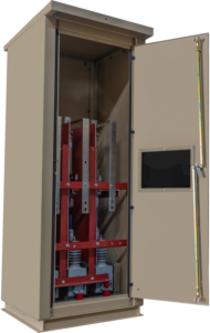
Current-Limiting Reactors: Reducing Fault Duty Without Replacing Switchgear
The letter arrives from the utility, and it is two paragraphs long. The ...
Specialty Products

Rex Power Magnetics Air Core Reactors are engineered to deliver reliable inductive performance for current limiting, harmonic filtering, and power quality improvement applications. With no magnetic core, these reactors provide linear reactance across a wide current range, eliminating magnetic saturation, core losses, and acoustic noise common in iron-core designs.
Each reactor is precision-wound using high-conductivity aluminum or copper conductors and supported by a high-strength fiberglass structure for mechanical stability and durability. The air-core construction ensures excellent thermal dissipation, stable inductance, and dependable operation under varying electrical and environmental conditions.
Rex Air Core Reactors are designed and tested to meet IEEE, CSA, and IEC standards, ensuring consistent performance and long service life in demanding industrial and utility environments.
Typical Applications Include:
Shunt Reactors: Compensate for capacitive currents in long transmission lines or cables, allowing more active power flow.
Current Limiting Reactors: Limit fault current magnitudes to levels compatible with existing protection systems.
Filtering Reactors: Used with capacitors and resistors to reduce harmonic content and improve power quality.
Neutral Grounding Reactors: Limit line-to-ground fault currents to controlled, safe values.
Rex Power Magnetics provides both standard and custom-engineered air core reactors to meet precise electrical and mechanical requirements.
| Capacity | up to 10,000kVAR |
| Voltage Class | up to 25kV |
| Cooling | Self Cooled (ANN / AN) |
| Frequency | 60Hz (50/60Hz Optional) |
| Conductors | Copper (Cu) or Aluminum (Al) Windings |
| Insulation System | 220°C Insulation System (150 °C Temp Rise Max) |
| Sound Level | Below 40dBA |
| Enclosure Type | Open Construction (Enclosure options available) |
| Enclosure Finish | ANSI 61 Grey Powder Coat |
| Testing | Std Production Tests per IEEE C57.16 & IEEE C57.32
Optional Type Tests
|
| Warranty | 12 Months (See Warranty and Limitations) |
| Quality System | ISO 9001:2015 Quality Management System |
| Certifications |
|
| Reference Standards |
|
An air core reactor is an inductive device that limits current, filters harmonics, or provides reactive impedance in an electrical system — without using a magnetic core. Instead of steel or laminated iron, it relies on the magnetic field created in free air around its coils to provide inductance. This eliminates core saturation, hysteresis losses, and magnetic coupling issues. Rex Power Magnetics air core reactors are designed for applications requiring stable inductance and linear performance under high current and harmonic conditions.
An air core reactor maintains a consistent inductance regardless of current magnitude, as there is no magnetic core to saturate. This makes it ideal for systems exposed to transient overcurrents, high harmonic distortion, or switching surges. Iron-core reactors, by contrast, experience reduced inductance and increased distortion at high currents due to core saturation. Air core designs offer superior linearity, thermal stability, and minimal magnetic coupling to nearby components — essential in precision filtering or high-energy circuits.
A Rex air core reactor is fundamentally a single-phase coil; a three-phase reactor consists of three coils arranged side by side or stacked vertically. Because there is no magnetic core to confine the flux, each coil interacts with the magnetic field of its neighbours. This mutual inductance can affect the reactance of each phase depending on the coil arrangement, spacing and winding direction.
In a vertical stack, the centre coil interacts with both neighbouring coils, while the outer coils interact with only one. Rex compensates for these differences through the coil design and spacing to maintain balanced reactance. Moving or rotating a coil during installation can change the reactance and affect performance.
Side-by-side arrangements are common for large current-limiting reactors, while vertically stacked configurations help reduce floor space. The specified arrangement and magnetic clearances must be maintained during installation. Standard outlines are available on the Enclosure Drawings page.
Unlike iron-core reactors, an air core reactor has no magnetic steel core and therefore produces no core losses. Its losses are load-dependent and come primarily from conductor resistance (I²R), eddy currents within the windings and stray losses induced in nearby metallic structures.
For series current-limiting reactors operating well below their rated current, losses are relatively low. Filter reactors carrying continuous fundamental and harmonic currents require closer loss evaluation, as higher-frequency harmonics increase eddy-current heating. Rex can adjust conductor sizing, winding construction and temperature-rise requirements to meet the application’s operating conditions.
Losses are measured at rated current during production testing under IEEE C57.16. For more information on the different loss mechanisms, see Understanding Losses in Transformers .
A dry-type Rex air core reactor eliminates the need for insulating oil, reducing maintenance requirements and removing concerns about oil leaks, containment systems and oil-related fire protection. Within its rated voltage and reactive power range, it can be installed indoors or outdoors with an appropriate enclosure.
The main considerations are magnetic clearance, physical size and insulation requirements. Unlike oil-immersed reactors, open air core designs produce an external magnetic field that requires adequate separation from nearby steel structures and conductive loops. Their cooling also depends on sufficient natural airflow.
For distribution-class current limiting, harmonic filtering and neutral grounding, dry-type air core reactors offer a practical, low-maintenance solution. For additional information, see Dry-Type vs. Liquid-Filled Transformers .
An air core reactor has no steel core to saturate, and therefore Its inductance depends only on coil geometry and the permeability of free space. The inductance is the same value at 10 percent, 350 percent and 1,000 percent of rated current, up to the mechanical and thermal limits of the winding. The only limit is the short-circuit withstand rating.
The difference matters in two places. In a current-limiting duty, an iron-core reactor that has lost half its inductance at 350 percent current lets through nearly twice the fault current the design predicted, and a breaker selected on the reduced value may be over-dutied. In a tuned filter, a 50 percent drop in inductance shifts the resonant frequency upward by about 41 percent, moving a 4.7th-harmonic filter to roughly the 6.6th and exposing the capacitor bank to the 7th harmonic. Neither is acceptable, so those duties use air core construction. Where currents stay within the saturation margin, the smaller iron-core unit from the Reactors & Filters category is the economical choice.
Each reactor consists of precision-wound aluminum or copper coils supported by a non-magnetic fiberglass or epoxy structure. The coils are dipped in polyester resin to increase mechanical strength, insulation stability, and environmental protection. The resin coating minimizes vibration, reduces corona discharge, and protects against moisture and contamination. The air core design ensures linear inductance, while the structural materials withstand high mechanical forces from short-circuit events and thermal cycling. Designs are optimized for low loss and long service life.
The main parameters include inductance (measured in millihenries or microhenries), rated current, voltage class, frequency, and thermal limit. The mechanical design considers magnetic forces, conductor spacing, and thermal dissipation. Rex Power Magnetics engineers design reactors with precise inductance tolerances and optimized coil geometry to meet each system’s electrical and mechanical requirements. Optional enclosures, terminal arrangements, and cooling enhancements can be specified for demanding applications.
Three current figures define a Rex air core reactor, and a complete specification states all of them.
Rated continuous current is the RMS current at rated frequency the reactor carries indefinitely at 40°C ambient without exceeding its 150°C average winding rise. Unlike a transformer, a reactor has no inherent overload allowance unless one is specified.
Rated short-circuit current is defined by IEEE C57.16 in two parts. The thermal rating is the symmetrical RMS current the winding can carry for a stated duration, commonly a few seconds, without exceeding the conductor temperature limit; the winding relies on its own thermal mass during the event. The mechanical rating is the peak asymmetrical current, including DC offset, whose electromagnetic forces the coil and supports must withstand without deformation. For a current-limiting reactor the mechanical rating is the governing design case, and the polyester-bonded, fiberglass-clamped winding is engineered for it.
Harmonic current applies to filter reactors. The specification should list the current at each harmonic order, because eddy losses rise with frequency and the fundamental alone understates heating. For neutral grounding reactors, IEEE C57.32 substitutes a short-time neutral current rating of 10 seconds or another stated duration plus a continuous rating for standing unbalance.
The Knowledge Hub article Short Circuit Testing of Transformers explains how mechanical withstand is verified on cored equipment; Rex applies the same principles to reactor design.
Tolerance is application-specific, and a Rex air core reactor is wound to the tolerance the specification states.
For a current-limiting reactor, the tolerance is normally one-sided: the reactance may exceed the rated value by a small margin but must never fall below it, because a low reactance means more fault current than the breaker study assumed. A slightly high reactance costs a little extra voltage drop and nothing else.
For a filter reactor, the tolerance is symmetrical, tight and matched between phases. The resonant frequency follows f = 1 / (2π√(LC)), so it varies with the inverse square root of inductance: a +5 percent inductance error moves the tuning down by about 2.4 percent, and −5 percent moves it up by 2.6 percent. On a filter tuned to the 4.7th harmonic (282 Hz at 60 Hz), that is a range of roughly 275 to 289 Hz. Capacitor tolerance and ageing add to the spread, so a tightly tuned 5th-harmonic filter is usually specified at ±3 percent or better on the reactor.
Rex holds tolerance by final turns adjustment and confirms it by the impedance measurement production test, reported on the test report. When the tuning frequency differs from 60 Hz, request the measured inductance at that frequency as well. The Calculators page and the Knowledge Hub article Impedance in Transformers support the arithmetic.
Consider a 13.8 kV switchgear bus with 25 kA symmetrical available fault current, feeding a 1,200 A feeder to a downstream lineup rated for 18 kA. A series air core reactor in the feeder must add enough reactance to hold the downstream fault below that rating; neglecting resistance and the downstream cable:
• Source reactance per phase: X_s = 7,967 V / 25,000 A = 0.319 Ω.
• Total reactance needed for 18 kA: X_t = 7,967 / 18,000 = 0.443 Ω.
• Reactor reactance: X_r = 0.443 − 0.319 = 0.124 Ω per phase.
• Inductance at 60 Hz: L = 0.124 / (2π × 60) = 0.33 mH per phase.
The nameplate would state 0.33 mH, 1,200 A continuous, 15 kV class with a matching BIL, and a short-circuit rating of 18 kA symmetrical for the relay clearing time. Reactive power at rated current is 3 × 1,200² × 0.124 = 536 kVAR, and on the feeder’s own base (7,967 V / 1,200 A = 6.64 Ω) it is a 1.9 percent reactor.
Two refinements belong in the real study: motor contribution downstream of the reactor is not limited by it, and the X/R ratio at the reactor terminals rises, increasing the DC offset the breaker must interrupt. The Knowledge Hub article Impedance in Transformers explains the per-unit conventions used above.
Air core reactors are widely used in harmonic filtering, capacitor bank protection, short-circuit current limiting, and line/load filtering in power systems. They are also used in renewable energy installations, DC link circuits, and drive systems to control inrush currents or dampen transients. Rex Power Magnetics designs these reactors for use in harmonic filters, tuned circuits, and custom power conditioning systems that demand high electrical accuracy and durability in continuous-duty environments.
Yes. When required, air core reactors can be supplied with ventilated NEMA 3R or 4 enclosures for outdoor use. The polyester resin coating and fiberglass support structure provide strong resistance to moisture, UV exposure, and corrosion. For extreme environments, additional epoxy sealing or stainless steel hardware can be used. Proper installation spacing and ventilation ensure adequate cooling and prevent magnetic interference with nearby metal structures.
Terminal connections on a Rex air core reactor must satisfy three requirements at once: carry rated and short-circuit current, avoid galvanic problems between metals, and keep conductors out of the magnetic field.
The terminals are pads on the coil’s top and bottom crossarms. On aluminum-wound units they are plated or fitted with bi-metallic plates so copper lugs or bus can be landed directly; do not connect bare copper to bare aluminum. Use flexible connectors or a short length of braid between the terminal and rigid bus so thermal expansion of the coil and electromagnetic movement during a fault are not transmitted into the bus supports.
Cable routing matters more than on a transformer. Any conductor running through or close to the field is subject to induced voltage and, in a shielded or armoured cable, circulating current in the shield or armour that can overheat the jacket. Keep conductors outside the magnetic clearance boundary on the drawing, bring them to the terminals radially rather than looping around the coil, and avoid forming a closed conductive loop with cable tray, conduit or ground conductors. Single-conductor cables should run with all three phases together.
Torque the terminal bolts to the manual’s value and verify the connection with a thermographic scan at load. The Knowledge Hub article Transformer Grounding and Bonding Explained covers the bonding of supports and enclosures, which applies equally here.
The 150°C maximum rise of a Rex air core reactor is referenced to a 40°C maximum ambient at altitudes up to 1,000 m, the same basis IEEE uses for dry-type transformers. Outside that envelope the rating is adjusted.
Altitude. Air density falls with altitude, so convection removes less heat and the dielectric strength of air clearances is reduced. IEEE dry-type practice derates the continuous current of self-cooled equipment by roughly 0.3 percent for each 100 m above 1,000 m; a reactor at 2,500 m therefore needs about 4.5 percent more current capacity in its design, or is operated at a correspondingly lower current. Air clearances also increase, which is a factor on 25 kV class units. Rex designs for the stated altitude rather than derating a standard coil.
High ambient. If the ambient exceeds 40°C, the rise must be lowered by the same amount, which means a larger coil or a lower continuous rating. State both the maximum ambient and the daily average.
Low ambient. Cold does not derate an air core reactor, but the polyester resin becomes more brittle, so thermal shock from cold start to full current should be avoided, and condensation during warm-up managed with heaters or a ventilated enclosure. The Knowledge Hub article Low-Ambient Temperature Considerations applies directly.
Commissioning a Rex air core reactor is a short procedure, but each step guards against a specific failure mode.
• Visual inspection. Check the resin coating for cracks or chips, confirm the spacer sticks are intact, and confirm no tools, packing or metal debris remain in the coil bore or between coils.
• Clearance verification. Measure the distance from the coil to the nearest steel, rebar, cable tray and enclosure panel against the drawing. Look for closed conductive loops that encircle the coil.
• Connection check. Verify terminal torque, bi-metallic plates where aluminum meets copper, and flexible connectors.
• Electrical verification. Measure winding resistance and compare with the test report, corrected for temperature; measure inductance and compare with the nameplate and between phases. A deviation indicates shipping damage or an installation that alters the mutual inductance.
• Insulation resistance between the coil and the support base, at a test voltage appropriate to the voltage class.
• First energisation. Energise, then survey the reactor and everything within the clearance boundary with a thermal camera after an hour at load. Hot spots on adjacent steel indicate an induced-current problem; hot spots on the coil indicate a connection problem.
Record all readings as the baseline for future maintenance. The Knowledge Hub article Transformer Commissioning: Critical Checks provides a comparable checklist for transformers on the same site.
In harmonic filter applications, air core reactors are connected in series with capacitors to form tuned or detuned filter banks. The reactor’s inductance limits the flow of harmonic currents into the capacitor, preventing resonance at harmonic frequencies and improving overall power quality. Because of their linear behavior, air core reactors maintain predictable filtering characteristics across the full operating current range, ensuring effective harmonic attenuation even under variable load conditions.
The detuning factor represents the reactor’s reactance as a percentage of the capacitor’s reactance at the fundamental frequency. It determines the tuning frequency of the reactor-capacitor combination and helps prevent unwanted resonance with harmonics in the electrical system.
On a 60 Hz system, common detuning factors include 5.67%, 7% and 14%, depending on the harmonic spectrum and required filtering performance. A higher detuning factor lowers the tuning frequency but also increases the voltage across the capacitor. For example, a 7% detuning factor raises the capacitor voltage to approximately 1.075 times the nominal system voltage, which must be considered when selecting the capacitor’s voltage rating.
The appropriate detuning factor should be confirmed through a harmonic study that considers capacitor tolerances, existing harmonic currents and potential system changes. Rex can design the air core filter reactor to meet the required inductance and current ratings. The Calculators page and Power Quality resources provide additional information on reactor selection.
Both limit line-to-ground fault current, but they behave differently during a fault and suit different systems.
A neutral grounding air core reactor is chosen where the fault current must remain high, typically 25 to 100 percent of the three-phase fault level. That is the regime for large generators, generator step-up transformer neutrals and utility distribution neutrals, where solid grounding would over-stress the machine or switchgear but relaying still needs a strong ground-fault signal. The reactor is compact because it stores energy rather than dissipating it, and its losses are low. Its limitation is the overvoltage criterion: if reactance is increased until fault current falls below about 25 percent of the three-phase value, arcing ground faults can produce transient overvoltages, so a reactor cannot be used for low-current grounding.
A neutral grounding resistor is chosen for low-resistance grounding at a few hundred amperes or high-resistance grounding at a few amperes, which is the norm for industrial medium-voltage distribution and mining. The resistor damps the transient rather than tuning it, so overvoltage is controlled at any fault level, at the expense of dissipating the full fault energy as heat for the rated time.
Where the system has no neutral, a grounding transformer supplies one and either device is connected to it. Rex builds the reactor under IEEE C57.32; the Knowledge Hub article Transformer Grounding: Understanding the Importance covers the system methods.
The product page lists 60 Hz standard with 50/60 Hz optional. Inductance is a property of coil geometry and does not change with frequency, so a Rex air core reactor rated in millihenries has the same inductance at either frequency. Everything derived from inductance does change.
Reactance scales directly with frequency, X = 2πfL, so the same coil presents five-sixths of its 60 Hz reactance at 50 Hz. A current-limiting reactor designed for 60 Hz lets through about 20 percent more fault current at 50 Hz, and a filter reactor that is 7 percent detuned at 60 Hz is 5.8 percent detuned at 50 Hz, moving the tuning order from 3.78 to 4.14 relative to the new fundamental. The kVAR absorbed by a shunt reactor at rated voltage rises by 20 percent at 50 Hz because the current rises.
There is no core to overheat, so unlike a transformer an air core reactor is not damaged by operation at the lower frequency; it simply does not deliver the same reactance.
Specify the reactance or tuning requirement at the actual system frequency. A unit ordered for dual frequency is designed so the reactance at the more demanding frequency satisfies the requirement, and the nameplate states both ratings. Export projects and marine duty installations with 50 Hz shipboard systems should state the frequency explicitly on the Product Configurator submission.
All three describe the same coil, but each is complete only with a stated base. The clearest specification for a Rex air core reactor gives the inductance in millihenries, the rated continuous current, the system voltage and the frequency. Inductance needs no base.
Percent reactance is convenient for current-limiting reactors because fault studies work in per-unit, but it must state its base. A “5 percent reactor” on a 1,200 A, 13.8 kV feeder base is 0.33 Ω; the same 5 percent on a 20 MVA transformer base at 13.8 kV is 0.48 Ω. Always give the current or MVA base alongside the percentage.
kVAR describes the reactive power at rated current, 3 × I² × X for a three-phase set, and is the natural rating for shunt reactors, which is why the product page expresses capacity as 10,000 kVAR. For a series or filter reactor, kVAR alone does not define the coil, because different current and inductance combinations give the same kVAR.
For filter reactors, an alternative is to state the capacitor bank rating and the tuning order or detuning factor and let Rex derive the inductance. Whatever form is used, Rex converts it and returns the inductance and current on the quotation for confirmation. The Knowledge Hub article Transformer Rating Explained discusses the parallel issue of kVA versus current ratings on transformers.
Yes. Rex Power Magnetics specializes in custom air core reactor designs for harmonic filtering, current limiting, or neutral grounding applications. Customization options include inductance value, current rating, physical dimensions, and mounting configuration. Engineering teams can also design reactors with specific tuning frequencies, voltage ratings, or dielectric clearances for utility, renewable energy, or industrial systems. Each custom-built reactor is fully tested for electrical, thermal, and mechanical compliance before delivery.
A Rex air core reactor has no core, no oil, no tap changer and no re-impregnation requirement, so maintenance is inspection and measurement rather than servicing. A practical programme, adjusted to the site, is:
• Every 6 to 12 months, energised: thermographic scan of the coil, terminals and structure within the clearance boundary, compared with the commissioning baseline. A rising terminal temperature indicates a loosening connection; a warm patch on the coil a developing turn problem; heat in adjacent steel something added inside the field.
• Every 12 months, de-energised: clean the coil surface and cooling ducts with dry compressed air, inspect the resin coating for cracks, chalking or tracking, check spacer sticks and insulators, and re-torque fasteners.
• Every 3 to 5 years, or after any through-fault: measure winding resistance and inductance and compare with the test report and previous readings. A resistance change beyond temperature correction indicates a conductor or joint problem; an inductance change indicates shorted turns or a displaced coil.
In contaminated or coastal environments, shorten the cleaning interval; conductive dust on the coil surface can track between layers. The Installation, Operation and Maintenance Manual gives the manufacturer’s procedure, and the Knowledge Hub article Transformer Maintenance: Essential Checklist covers the shared elements of a substation programme.
Each symptom on an air core reactor points to a small number of causes.
Coil running hot overall. The most common cause is current above rating, usually because the harmonic spectrum has grown; measure the RMS current with a true-RMS analyser and compare with the nameplate. Blocked cooling ducts and obstructed airflow are the next candidates, followed by steel or an enclosure added inside the field.
Localised hot spot. A hot terminal is a loose or corroded connection, particularly an aluminum-to-copper joint made without a bi-metallic plate. A hot band on the coil is a turn-to-turn short, confirmed by an inductance measurement lower than the test report; the reactor must be removed from service.
Increased noise. Loose spacer sticks or cracked resin let the turns move, and the noise appears at 120 Hz. New harmonic tones mean the current spectrum has changed. A rattle from the enclosure is induced vibration in a loose panel.
Filter detuning or capacitor fuse operations. If branch current at the tuned harmonic has fallen while bus distortion has risen, either capacitor units have failed, changing C, or the reactor inductance has changed, usually through a mechanical shift of stacked coils. Measure both.
Any deviation from the test report should be reported to Rex through the Contact page before re-energising. The Knowledge Hub article Transformer Failures: Causes, Faults and Prevention addresses the analogous transformer symptoms.
Because every Rex air core reactor is designed to order, the nameplate and test report together are the definitive record of what was built. The nameplate, prepared to IEEE C57.16 or C57.32 conventions, carries the Rex serial number, rated inductance or reactance and tolerance, rated continuous current, rated frequency, system voltage and insulation class with BIL, the thermal and mechanical short-circuit ratings with duration, temperature rise and insulation system class, cooling designation, connection (single-phase or three-phase with arrangement), conductor material, weight and the applicable standard. A neutral grounding reactor also states the short-time neutral current and duration. Filter reactors list the rated harmonic spectrum where it was part of the design.
The production test report records measured winding resistance per phase at a stated temperature, measured inductance or impedance per phase at rated frequency, measured losses at rated current, and the turn-to-turn test result. Where type tests were ordered, the certified impulse, chopped-wave, withstand, temperature-rise and sound-level results are attached.
To verify a unit on site, measure resistance corrected to the report’s temperature and inductance at rated frequency, and confirm the phases agree with the report within tolerance. Retain the report with the commissioning records as the baseline for maintenance. Copies are available through the Documentation page, and the Knowledge Hub article Understanding Transformer Nameplates explains the shared fields.
Rex air core reactors are designed to order rather than selected from a fixed catalogue. To request a quotation, provide the intended application, required inductance or reactance, continuous current, system voltage, frequency, harmonic spectrum and operating environment. Short-circuit ratings, insulation requirements and any special testing should also be specified.
Rex engineering reviews these requirements and prepares a quotation outlining the proposed design, ratings, conductor material, dimensions, weight and testing requirements. Following order confirmation, an approval drawing is provided showing the coil arrangement, mounting details, terminal locations and required magnetic clearances.
Once the design is approved, the reactor is manufactured, assembled and tested according to the agreed specifications. Lead time depends on the design complexity and testing requirements. Submit your specifications through the Product Configurator or Get a Quote page.
Wednesday, 2 September 2026
The letter arrives from the utility, and it is two paragraphs long. The ...
Thursday, 2 April 2026
Inductors—often referred to as reactors in power system applications—are used to store energy ...
Tuesday, 2 December 2025
Grounding is a foundational aspect of power system design. It stabilizes phase voltages, ...