Updated: August 17th, 2026
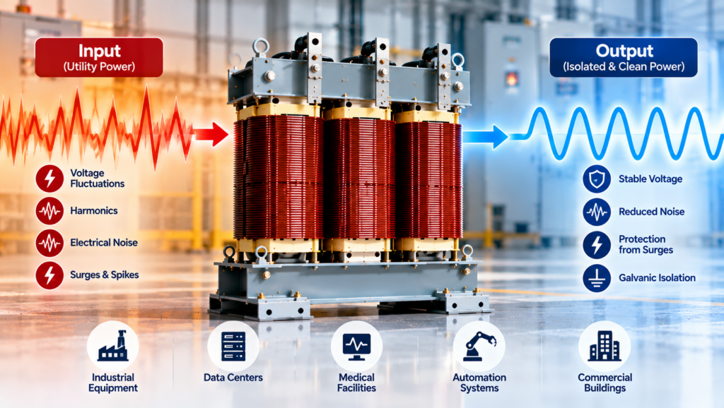
An isolation transformer is often added to a specification with several expectations attached to it: safer equipment, cleaner power, fewer grounding problems, and better protection for sensitive loads. Those outcomes are possible, but they do not come from the word “isolation” alone.
The transformer first provides a defined electrical function. Separate primary and secondary windings transfer power through the magnetic field while preventing a direct conductive connection between the source circuit and the load circuit. What that separation accomplishes depends on the secondary grounding arrangement, winding configuration, electrostatic shielding, connected equipment, and disturbances present in the system.
This distinction matters during transformer sizing and selection. A general-purpose unit, a drive isolation transformer, and a transformer intended for a medical isolated-power system may all provide galvanic isolation, but they are not interchangeable.
What Electrical Isolation Actually Means
In a two-winding isolation transformer, the primary and secondary conductors are physically separated by insulation. An alternating voltage applied to the primary creates changing magnetic flux in the core. That flux induces a voltage in the secondary without requiring a metallic path from one winding to the other.
The voltage ratio is determined by the turns ratio:
Vₛ ÷ Vₚ ≈ Nₛ ÷ Nₚ
where Vₛ and Vₚ are the secondary and primary voltages, and Nₛ and Nₚ are the corresponding numbers of turns.
If both windings have the same number of turns, the transformer is nominally 1:1. That arrangement is useful when the load requires the same nominal voltage as the source but a separate electrical circuit. Isolation transformers can also be step-up or step-down units. A 600 V to 208Y/120 V distribution transformer, for example, provides voltage conversion and galvanic isolation at the same time.
This is also why an isolation transformer is not the opposite of a power transformer. It is a transformer construction with separate windings, and it may perform ordinary power-distribution duties. The more useful comparison is with an autotransformer. An autotransformer uses a shared winding and therefore offers a smaller, often more economical means of changing voltage where source-to-load isolation is not required. That shared electrical path is precisely what an isolation transformer avoids.
Isolation Does Not Make the Secondary Harmless
The most serious weakness in simplified explanations of isolation transformers is the suggestion that a person can touch an isolated secondary conductor without risk. That is not a safe design assumption.
An intentionally ungrounded secondary may have no solid reference to ground under normal conditions. A first line-to-ground fault can therefore behave differently than it would on a grounded system. However, the secondary still has full voltage between its conductors. Contact with both conductors can complete the circuit through the body, and capacitive coupling, connected equipment, insulation leakage, or an existing ground fault can create additional current paths.
Many isolation transformers do not operate with a floating secondary at all. Their secondary is grounded and bonded as required for the installation, creating a new local voltage reference and a defined fault-current path. This arrangement allows protective devices to respond predictably when a secondary conductor faults to bonded metal. Rex’s guide to transformer grounding and bonding explains why the grounding electrode connection, system bonding point, equipment bonding, and neutral treatment have to be considered together.
Galvanic isolation can prevent a primary-side ground reference from being carried directly into the secondary circuit. It does not replace overcurrent protection, equipment grounding, bonding, guarding, insulation, or safe work procedures. The transformer and its secondary system must be installed according to the applicable code and engineered grounding design.
Why Isolation Can Improve Noise Performance
Electrical isolation is useful in power-quality work because it removes the direct conductive path between the primary and secondary circuits. That does not mean every disturbance is blocked.
The transformer readily transfers the intended 50 or 60 Hz power through magnetic coupling. Differential-mode disturbances appearing between the primary conductors can also couple through the turns ratio. Low-frequency voltage sags, swells, and waveform distortion are not automatically corrected. Harmonic current drawn by a nonlinear load still affects transformer heating and can distort the secondary voltage.
A standard isolation transformer should therefore not be described as a surge suppressor, harmonic filter, or voltage regulator. Rex’s guide to industrial power quality and transformers explains why the disturbance has to be identified before a mitigation method is selected.
High-frequency common-mode noise behaves differently. Even though the windings are insulated from one another, parasitic capacitance exists between them. Fast disturbances can couple across that capacitance from the primary circuit to the secondary circuit.
An electrostatic shield placed between the windings provides a controlled path that diverts part of this capacitively coupled current to ground. The shield can improve common-mode noise attenuation, but its performance depends on its construction, grounding, frequency range, and the impedance of the complete installation.
Rex’s article on electrostatic shields in transformers examines both the benefits and limits of electrostatic shielding.
An electrostatic shield reduces capacitive coupling between windings. A surge protective device limits transient overvoltage, while a filter or reactor targets specific frequencies or switching disturbances. A K-factor transformer is designed to withstand the additional heating caused by harmonic currents, whereas a harmonic-mitigating transformer is designed to reduce certain harmonic effects. These features may be combined in one system, but none should be assumed merely because the transformer has separate windings.
Ground Loops Require a Complete-Circuit View
A ground loop exists when multiple conductive paths between nominally grounded points allow unwanted current to circulate. The resulting voltage differences may appear as hum in audio systems, measurement error in instrumentation, communication problems, or unstable control signals.
An isolation transformer can interrupt one conductive path and establish a secondary circuit with a controlled reference. This is often useful when equipment needs to be supplied from a separately derived source or when noise is entering through the power connection.
It does not follow that every ground loop disappears. Signal-cable shields, communication conductors, equipment bonding conductors, building steel, and other interconnected equipment may preserve parallel paths.
Removing a required protective ground to stop noise is not an acceptable solution. The source of the circulating current and every return path must be identified before deciding whether power isolation, signal isolation, revised bonding, cable-routing changes, or another measure is appropriate.
Where General-Purpose Isolation Transformers Fit
In commercial and industrial distribution, isolation transformers commonly supply lighting panels, machine tools, heating, ventilation and air-conditioning equipment, control systems, instrumentation, and general building loads. The transformer may change voltage, create a new secondary system, provide a neutral through the selected winding connection, and prevent the primary circuit from continuing directly into the load circuit.
For these applications, general-purpose isolation transformers are selected around the system voltage, kVA, phase, frequency, connection, impedance, temperature rise, enclosure, and installation environment. Shielding or non-standard electrical characteristics can then be added when the application establishes a need for them.
Sensitive electronic loads are sometimes placed on an isolation transformer to reduce common-mode coupling or separate them from a noisy distribution segment. The improvement depends on identifying the actual disturbance. If the problem is a deep voltage sag, repetitive switching transient, harmonic-rich current, or an incorrectly bonded circuit, installing a standard isolation transformer alone may leave the underlying problem unchanged.
Drive Loads Need More Than General-Purpose Isolation

Variable-frequency drives and other power-electronic converters place different electrical and thermal demands on a transformer than ordinary linear loads. Their rectifier front ends draw nonsinusoidal current, increasing harmonic loss and affecting voltage waveform quality. The system may also be exposed to commutation notches, switching-related disturbances, and common-mode current.
A drive isolation transformer is engineered for this duty. Its winding configuration, thermal capacity, impedance, shielding, and flux density can be selected for the drive topology and load profile. It can also provide the voltage transformation or phase relationship required by the drive system.
This specialized construction should not be confused with equipment installed between a drive output and a motor. Output reactors, dV/dt filters, and sine-wave filters address cable-side and motor-side switching effects and perform different functions. The correct component depends on whether the disturbance is on the drive input, within the conversion process, or at the motor terminals.
Medical Isolation Is a Specialized System
Hospitals are frequently cited as a general example of isolation-transformer use, but the application requires more precision. A standard commercial isolation transformer is not automatically suitable for patient-care power.
A medical isolated-power system includes more than a transformer. Its design may require an ungrounded secondary, controlled leakage and capacitance, continuous insulation monitoring, appropriate distribution equipment, alarms, and application-specific testing.
The IEC 61558-2-15:2022 standard addresses isolating transformers specifically intended for medical IT systems supplying medical locations. In this context, “IT” identifies the system’s relationship to earth; it does not mean information technology. Applicable Canadian or local health-care electrical requirements must also be established for the project.
The purpose of this arrangement is not to declare the circuit shock-proof. It is to control ground-fault behaviour and continuously indicate deterioration of the system’s isolation so that service continuity and electrical safety can be managed in the way required for the medical location.
The same caution applies to other specialized environments. Laboratories, data centres, renewable-energy systems, uninterruptible power supplies, and test benches may use isolation transformers, but their power architectures differ. The presence of sensitive or expensive equipment does not by itself define the required transformer.
What Has to Be Specified
The first specification question is the function the transformer must perform. Is the objective to change voltage, create a separately derived system, supply a neutral, interrupt a conductive noise path, attenuate common-mode noise, serve nonlinear loads, or meet the requirements of a specialized isolated-power system? A project may have more than one objective, but each must be stated.
The electrical design then has to define primary and secondary voltages, kVA, phase, frequency, winding connection, grounding arrangement, taps, impedance, regulation, inrush performance, and available fault current. Load characteristics matter as much as steady-state kVA. Motors, drives, rectifiers, uninterruptible power supplies, and high-inrush control devices can require different thermal or transient performance.
Environmental and mechanical requirements also affect the design. Ambient temperature, altitude, ventilation, contaminants, moisture, enclosure rating, sound limits, seismic requirements, conductor-entry locations, and available space can all change the practical transformer selection.
If power-quality improvement is part of the reason for the transformer, the specification should identify the disturbance and expected performance. “Clean power” is not a measurable requirement. Common-mode attenuation, interwinding capacitance, shield arrangement, harmonic load profile, surge environment, and required protective devices provide a much stronger engineering basis.
Conclusion: Isolation Must Be Defined at the System Level
An isolation transformer does one thing inherently: it transfers power between separate windings without a direct conductive source-to-load connection. That capability is valuable, but its system effect depends on how the transformer is designed, grounded, protected, and connected.
The secondary may be grounded or intentionally ungrounded. The turns ratio may be 1:1, step-up, or step-down. An electrostatic shield may reduce common-mode coupling, but it does not correct every power-quality disturbance. A medical isolated-power system requires equipment and monitoring beyond a general-purpose transformer, while a drive load requires construction matched to its harmonic and transient duty.
The right selection starts by replacing the broad request for “isolation” with a defined electrical objective. Once the source, load, grounding method, disturbance environment, and required standards are clear, the transformer can be designed to provide the isolation the system actually needs.
