

Monday, 14 September 2026
DOE 2029 vs. NRCan: Where U.S. and Canadian Transformer Efficiency Rules Diverge
A 300 kVA three-phase low-voltage dry-type transformer built to 99.02% efficiency can satisfy ...
Low Voltage Distribution Transformers

Rex Power Magnetics Harmonic Mitigating Transformers (HMTs) are designed to enhance power quality and system reliability in electrical networks supplying non-linear loads such as variable frequency drives (VFDs), UPS systems, and other electronic equipment. By effectively reducing current and voltage distortion, these transformers help maintain balanced loading, minimize neutral currents, and extend the life of connected equipment.
Rex HMTs utilize two advanced design principles to achieve superior harmonic performance:
Zero Sequence Flux Cancellation:
The secondary windings are specially configured so that zero sequence fluxes — primarily the 3rd, 9th, and 15th current harmonics — cancel out internally without being drawn from or circulating in the primary delta winding. This flux cancellation provides a low-impedance path for zero-sequence harmonics, significantly reducing voltage distortion and transformer losses.
Phase Shifting:
Non-triplen harmonics such as the 5th, 7th, 11th, and 13th are mitigated through phase-shifting techniques on the secondary side. Depending on the selected arrangement (single, dual, or triple output), specific harmonic currents are effectively cancelled before they couple into the primary winding.
The result is cleaner power, higher efficiency, and lower operating temperatures — ensuring stable, reliable performance in harmonic-rich environments.
| Capacity | 15 to 1,000kVA Three Phase |
| Voltage Class | 1.2kV |
| Cooling | Air Cooled (ANN) |
| Frequency | 60Hz (50/60Hz Optional) |
| Conductors | Copper (Cu) or Aluminum (Al) Windings |
| Temperature Rise | 150°C (115°C or 80°C Optional) |
| Insulation System | 220°C |
| Impregnation | Polyester Resin Dipped and Baked |
| Efficiency | Meets North American Energy Efficiency Standards:
|
| K-Factor | Suitable for non-sinusoidal current load with a K-factor not to exceed 4 (K9, K13, K20 Optional) |
| Primary Taps | Typically +/-2 x 2.5% taps (refer to dry type distribution transformer catalogue) |
| Configuration | Single, Dual or Triple output |
| Sound Level | Meets NEMA ST-20 |
| Enclosure Type | Type 1 or 3R Indoor (refer to catalog) |
| Enclosure Finish | ANSI/ASA 61 Grey |
| Warranty | 12 Months (See Warranty and Limitations) |
| Quality System | ISO 9001:2015 Quality Management System |
| Certifications |
|
| Reference Standards |
|
| Optional Features & Accessories |
|
A harmonic mitigating transformer (HMT) is specifically engineered to reduce current and voltage distortion caused by non-linear loads such as variable frequency drives (VFDs), rectifiers, and computer equipment. Unlike standard K-Factor transformers, which are designed to tolerate harmonics, an HMT actively cancels certain harmonic components—particularly triplen (3rd, 9th, 15th)—through phase-shifting and winding configuration. Rex Power Magnetics HMTs improve power quality, enhance system efficiency, and reduce heating in conductors and equipment, making them ideal for modern facilities with high electronic load density.
An HMT uses phase-shifted secondary windings—typically ±15°, ±30°, or other engineered configurations—to produce currents that are out of phase with harmonic components generated by non-linear loads. When multiple transformers feed a common panel, these phase shifts cause triplen harmonics to cancel in the line conductors, significantly reducing total harmonic distortion (THD). The winding geometry, core design, and internal shielding are optimized to minimize losses and suppress both current and voltage harmonics without requiring external filters or active components.
HMTs are used in facilities with significant non-linear or electronic loads—such as data centers, commercial buildings, hospitals, educational institutions, and industrial plants using drives or PLCs. They are installed in power distribution systems supplying equipment like VFDs, servers, and LED lighting systems. In multi-transformer systems, they are configured in pairs or groups with specific phase displacements to achieve harmonic cancellation across large sections of the network. This results in improved voltage stability, reduced heating, and enhanced reliability of electrical infrastructure.
It`s normal for new transformers to release some harmless odors from the varnish impregnation used in the coils for a week or two after energization. Older Transformers can also release some odor if loaded to a higher level than they have experienced previously in their history.
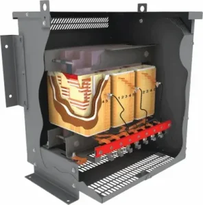
In a conventional delta-wye transformer, the 3rd, 9th and 15th harmonic currents drawn by single-phase electronic loads are in phase on all three phases, so they add in the neutral and produce a zero-sequence flux in each core leg. That flux induces a circulating current in the primary delta, which heats the primary winding and drops a distorted voltage across the transformer impedance. In a Rex Harmonic Mitigating Transformer the secondary is wound in two sections on different core legs, so the zero-sequence ampere-turns of one section oppose those of the other and the net zero-sequence flux is close to zero. The triplen currents still flow in the secondary conductors and neutral, but they see a very low zero-sequence impedance and are not reflected into the primary. The primary delta is still needed for the fundamental: it supplies the path for balanced three-phase magnetizing and load current and provides the isolation that makes each output a separately derived system. The Knowledge Hub article Harmonic Mitigating Transformers: How to Improve Power Quality shows the winding arrangement and flux diagrams, and Wye vs. Delta covers the conventional connection it improves on.
The nameplate kVA of a Rex Harmonic Mitigating Transformer is the total through-put of the primary; the outputs share it. A 300 kVA dual-output unit is normally built as two 150 kVA secondaries, and a 300 kVA triple-output unit as three 100 kVA secondaries, each with its own neutral and terminal set. The split is equal by default because harmonic cancellation between outputs depends on the phase-shifted currents having similar magnitude, but Rex can build unequal splits when the panel schedule is known and cannot be balanced. Each output is a separate 208Y/120 V, 480Y/277 V or other wye system, so each must be sized, protected and grounded on its own kVA, not the nameplate total. The full nameplate can be drawn only when the outputs are loaded together; loading one output of a 300 kVA dual unit to 250 kVA is an overload of that secondary even though the primary is well within rating. When the loads on the outputs will grow at different rates over the building’s life, specify the split for the end-state schedule and confirm it with Rex through the Product Configurator. The Transformer Rating Explained article covers the general rating conventions.
Cancellation happens between winding sections and between outputs, but the current in each secondary conductor is still the distorted current the loads draw. The secondary windings and neutrals of a Rex Harmonic Mitigating Transformer therefore experience the same eddy-current heating as any transformer feeding the same loads; what the HMT removes is the harmonic heating in the primary and the circulating triplen current in the delta. The standard design is rated for a load K-factor not exceeding 4, which covers the typical commercial mix once the primary-side losses are removed. Order K9, K13 or K20 when the metered load spectrum is above K4 on the secondary side regardless of what happens upstream: dense server or workstation panels, a floor of six-pulse drives without chokes, or rectifier loads. The K rating on an HMT is applied to the secondary conductor design, and it does not change the phase-shift arrangement. If the survey shows a high K-factor but the compliance problem is at the point of common coupling, the HMT still does the cancelling; the K rating only ensures the unit runs at its nameplate rise while doing so. K-Factor Transformer Explained describes how the K-factor is calculated from the spectrum.
Both, but through different mechanisms, which determines which output arrangement to specify. Single-phase switch-mode loads such as servers, workstations, LED drivers and small UPS units draw current dominated by the 3rd harmonic, with 5th, 7th and 9th behind it. On a 208Y/120 V or 480Y/277 V panel, the zero-sequence flux cancellation built into every Rex Harmonic Mitigating Transformer removes the 3rd, 9th and 15th from the primary regardless of how the loads are split, so even a single-output 0° unit gives a large improvement on these loads. Three-phase six-pulse VFDs and rectifiers draw no triplens when balanced; their spectrum is 5th, 7th, 11th and 13th, which only phase shifting removes. Those loads need a dual-output unit with 30° between outputs, or a pair of units with complementary displacements, and the drives must be divided between the two outputs. A mixed floor with both load types gets the best result from a dual or triple output unit, with single-phase loads spread evenly and drives split across outputs. The Power Quality industry page describes the survey Rex uses to sort the load, and Understanding Harmonics and IEEE 519 explains the spectra.
The two cancellation mechanisms degrade differently. Zero-sequence flux cancellation in a Rex Harmonic Mitigating Transformer is a property of the winding, not of the load, so triplen harmonics are kept out of the primary whether the non-linear share is 10 percent or 100 percent and whether the outputs are balanced or not. Phase-shift cancellation of the 5th, 7th, 11th and 13th depends on the two phase-shifted currents being of similar magnitude: if one output of a 30° dual unit carries 80 percent of the drive load and the other 20 percent, only the portion that has a partner is cancelled and roughly 60 percent of the 5th and 7th current passes to the primary. Linear load on either output neither helps nor hurts the cancellation; it simply dilutes the percentage distortion at the primary. In practice, aim to keep the non-linear kVA on paired outputs within about 20 percent of each other and revisit the panel schedule when loads are added. Where the load cannot be balanced, a triple-output unit spreads the risk across three displacements. Rex engineering will estimate the residual distortion for a given split when the survey is submitted with a quote request. The Electrical Power Quality article covers how unbalance shows up in measurements.
Yes, and this is the most common retrofit. A General Purpose Isolation Transformer feeding a panel of workstations, monitors and LED lighting carries the 3rd harmonic as a circulating current in its delta primary, runs warmer than its linear-load rating suggests and passes voltage distortion to the panel. A single-output 0° Harmonic Mitigating Transformer of the same kVA and voltages is a physical drop-in for the same duty: it has the same 1.2 kV class, 220°C insulation, 150°C rise, ±2 × 2.5 percent primary taps, Type 1 or 3R indoor enclosure and CSA/UL certification, and the same primary and secondary conductor terminations. What changes is inside: the secondary winding arrangement, which makes the unit somewhat larger and heavier for the same kVA, and the neutral, which should be brought out at full phase-conductor capacity because the triplen current still flows in it. The HMT is also not built through the Part Number Builder used for general purpose units; it is configured with Rex through the Product Configurator, where the output arrangement is selected. If the existing unit is on a floor with several similar transformers, the retrofit is the moment to give them complementary displacements so the 5th and 7th cancel as well. The Isolation Transformer article describes what the general purpose unit delivers on its own.
Unless designed for special service conditions / environments, below are the standard service conditions for dry type distribution transformers:
To ensure proper operation, avoid installing transformers in environments with excessive moisture, extreme temperatures, or direct sunlight. Maintain recommended clearances and keep all ventilation panels unobstructed.
Each transformer is built with high-grade silicon steel cores and precision-wound copper or aluminum conductors. The core and coil assemblies are dipped in polyester resin, which provides mechanical rigidity, improved dielectric strength, and moisture resistance. The winding configurations are designed for specific phase-shifted performance and optimized for thermal management under harmonic loading. Electrostatic shielding can be included to further minimize common-mode noise. This construction ensures long life, low vibration, and high electrical performance in continuous-duty environments.
Rex Power Magnetics offers harmonic mitigating transformers in a variety of phase-shift configurations, including 0°, ±15°, and ±30° displacements. These shifts are selected based on load profile and the number of transformers operating in parallel. For example, a +15° and –15° pair can effectively cancel 3rd, 9th, and 15th harmonics when supplying balanced three-phase loads. Custom winding connections and vector group designs are also available to achieve optimized harmonic cancellation for specific systems.
Temperature rise refers to average increase of temperature of the transformer windings at full load above the ambient temperature. when operating at full load. In addition to the average temperature rise of the windings, transformers also experience a “hot spot” temperature, which refers to the highest temperature point in the windings.
For example, a transformer with a 220°C insulation system may be designed with a 150°C average temperature rise and a 30°C hot spot allowance. This means that Above a 40C ambient, the total absolute temperature will not exceed 220°C. Transformers with lower temperature insulation systems (180°C or 200°C) will be designed with lower temperature rises (115° or 130°C) and hot spots so they can be installed in the same ambient temperature and still not exceed the temperature rating of the insulation system.
The table below shows the maximum average winding temperature rise, maximum hot spot temperature rise and maximum winding temperature for the most common insulation classes. Note that these are based on a max average ambient of 30°C during any 24-hour period and a maximum ambient of 40°C at any time.
| Insulation Class | Insulation Class | Average Winding Temperature Rise |
Hot Spot Temperature Rise |
Maximum Winding Temperature |
| Class 180 | F | 115°C | 145°C | 180°C |
| Class 200 | N | 130°C | 160°C | 200°C |
| Class 220 | H | 150°C | 180°C | 220°C |
Customers occasionally specify a transformer of a particular insulation class to be designed with an average temperature rise below the average temperature rise values shown in the table above. The benefits of doing so include:
Rex Power Magnetics’ ventilated distribution transformer terminals are rated 90°C. Conductors with at least a 90°C insulation rating at or below their 90°C ampacity rating should be utilized.
Displacement on a Rex Harmonic Mitigating Transformer is stated as the angle of each secondary line-to-neutral voltage relative to the primary line-to-line voltage, using the conventional delta-wye 30° as the reference. The standard offerings are 0°, +15°, −15°, +30° and −30°; a 0° output is the same phase relationship as a conventional delta-zigzag and a −30° output matches a conventional delta-wye. On a dual-output unit the two outputs are typically 0° and −30°, giving 30° between them. The approved outline and connection drawing shows each output’s vector diagram and terminal designations, and the nameplate lists the displacement of each output so that a future electrician does not parallel it with a conventional unit. When ordering, state the displacement required for each output explicitly rather than relying on a description such as “dual output”; the same arrangement can be built with different absolute angles depending on what other transformers share the upstream bus.
The positive-sequence impedance, the figure on the nameplate and the one used for fault-current and voltage-regulation calculations, is set by the design in the same way as any Rex dry-type unit and is confirmed on the approval drawing for each rating; Rex can design to a specified value where a coordination study requires it. A Harmonic Mitigating Transformer differs from a delta-wye unit in its zero-sequence impedance, which is deliberately low because the two secondary winding sections on different core legs cancel the zero-sequence flux. This is what gives triplen harmonics their low-impedance path and reduces voltage distortion at the panel, but it has two consequences for the protection engineer. First, the line-to-neutral fault current at the secondary terminals is higher relative to the three-phase fault current than on a delta-wye of the same rating, so the neutral, the bonding jumper and the interrupting rating of single-pole devices should be checked against the line-to-neutral value, not just the three-phase value. Second, secondary voltage regulation under unbalanced single-phase load is better than a conventional unit. Both figures are provided on request for the specific design. Use the Calculators for first-pass fault estimates and see Transformer Impedance: Impact on Fault Current and Voltage for the method.
The standard tap arrangement on a Rex Harmonic Mitigating Transformer is two 2.5 percent taps above and two below nominal on the primary winding, giving a ±5 percent adjustment range in 2.5 percent steps; larger ratings follow the same pattern as the rest of the family and are confirmed on the drawing. Because the taps are on the primary and all outputs are wound on the same core, changing tap moves every output voltage by the same percentage and leaves the angular displacement and the ratio between outputs unchanged. Tap changes are made de-energized by relinking the primary tap terminals, and all three phases must be on the same tap; a mismatch produces a circulating fundamental current in the delta and an unbalanced output. Set the tap from a measurement of the actual primary voltage at typical load: a 600 V system that sits at 615 V under light load should be on the +2.5 percent tap so that the 208Y/120 V outputs are not chronically high, which matters for LED drivers and switch-mode supplies whose current distortion increases with peak voltage. Do not use taps to correct a difference in voltage between two outputs; that indicates unequal loading, not a transformer problem. Transformer Tap Changers: Purpose, Operation and Practical Use covers the procedure, and the Transformer Turns Ratio Formula article shows how to check the result.
The 150°C standard rise on a Rex Harmonic Mitigating Transformer is the average winding rise at nameplate kVA with the design K4 load in a 30°C average, 40°C maximum ambient, under a 220°C insulation system with a 30°C hot-spot allowance. Cancellation removes the triplen circulating loss from the primary and the associated stray losses, so an HMT feeding a given electronic load runs cooler than a delta-wye of the same rise class on the same load, but the rated rise itself is still reached when the unit is fully loaded with a K4 spectrum. Specifying 115°C or 80°C rise buys the same three things it does on any Rex dry-type unit: lower operating temperature and longer insulation life, more headroom in a warm electrical room or at altitude, and short-term overload capability. For HMTs the lower rise has a fourth use. Output loading changes as tenants and equipment change, and a unit ordered at 80°C rise tolerates one output being loaded well past its nominal share for a period without exceeding the 220°C system limit. Where the ambient is controlled and the load is well defined, 150°C rise with the correct K rating is the economical choice; where the electrical room runs warm or the load is expected to grow, 115°C rise is the usual compromise. See Transformer Insulation Classes and Thermal Management in Dry-Type Transformers.
An electrostatic shield is a grounded conductive layer between primary and secondary windings that intercepts the capacitive path through which high-frequency common-mode noise crosses the transformer. Rex Harmonic Mitigating Transformers can be built with a single, double, triple or multiple (ultra) shield. A single shield between the windings is adequate for most commercial installations where the aim is to keep switching noise from workstations and drives off the upstream distribution, and it is the arrangement to specify when in doubt. Double and triple shields add layers between and around winding sections, reducing the residual capacitance further and improving attenuation across the frequency range typical of drive carrier frequencies and their harmonics. The multiple or ultra shield arrangement wraps individual winding sections, which is specified for laboratory, medical imaging, broadcast and test-bench feeds where common-mode noise must be held to very low levels. The shield does not affect the harmonic cancellation, the impedance or the efficiency rating, and it is grounded at the transformer enclosure with its own terminal; leave that terminal connected even if a separate shield ground is not shown on the drawing. Specify the shield in the Product Configurator with the rest of the configuration. How Electrostatic Shields Reduce Transformer Noise explains the mechanism in more detail.
Any transformer which is not installed and energized immediately should be stored in a dry, clean space having a uniform temperature to prevent condensation on the windings. Dry type transformers with resin dipped or epoxy vacuum impregnated coils can be stored at ambient temperatures as low as -50C. Transformers with encapsulated or epoxy cast coils should not be stored at ambient temperatures below -20C to prevent cracking of the epoxy. Preferably, transformers should be stored in a heated building having adequate air circulation and protected from cement, plaster, paint, dirt, and water or other gases, powders, and dust. The floor on which the transformer is being stored should be resistant to the upward migration of water vapor. Precautions should be taken to prevent storage in an area that water could be present, such as roof leaks, windows, etc. Condensation or absorption of moisture can be greatly reduced by keeping the transformer enclosure 5⁰C-10⁰C above ambient temperature. This can be easily achieved by the installation and energization of space heaters (optional). If the transformer is not furnished with internal space heaters, then external, portable heaters can be used. Note: Lamps or heaters should never come in direct contact with the transformer coil insulation.
It is not advisable to store a dry type transformer outdoors, but in the case that it is unavoidable, protective measures should be taken to prevent moisture and foreign debris from entering the transformer enclosure. The plastic wrapping supplied during shipment should be left in place, and a suitable drying agent such as silica gel packs should be used. The unit should also be checked periodically for indications of condensation on the windings, coil support blocks, core, core clamping system and bus/cables.
In dry-type transformers, the surrounding air plays a critical role in their operation. Generally, low ambient temperatures do not negatively impact an energized transformer, as the no-load losses typically generate enough heat to maintain proper conditions, even in environments as cold as -30°C. However, transformers stored at low temperatures present two primary concerns:
Rex Power Magnetics recommends testing transformers (megger testing), warming them to above 0°C, or following a drying-out procedure if moisture is suspected. Refer to Rex Power Magnetics’ cold start procedures to ensure safe energization in cold conditions. Energizing a transformer with compromised insulation due to moisture can cause damage and potential safety hazards.
The minimum required clearances of a dry type transformer to walls, floors or other equipment must adhere to the local electrical code requirements.
In the absence of such requirements, Rex Power Magnetics recommends that dry type transformers be mounted so that there is an air space of no less than 150mm (6”) between the enclosures, and between the enclosure and any adjacent surface except floors. When the adjacent surface is a combustible material, the minimum permissible separation between the transformer enclosure and the adjacent surface should be 300mm (12”). Where the adjacent surface is the wall on which the transformer is mounted, the minimum permissible separation between the enclosure and the mounting wall should be 6mm (0.25”) so long as the surface is of a non-combustible material.
Each wye output of a Rex Harmonic Mitigating Transformer is its own separately derived system under the CEC and the NEC, so each needs its own system bonding jumper from its neutral point to the transformer enclosure and grounding electrode conductor, and the two or three neutrals must never be connected together downstream. Size each neutral for the full phase conductor ampacity of that output, not a reduced value: the HMT keeps triplen current out of the primary, but that current still flows in the secondary neutral, and on a panel dense with single-phase electronics the neutral can carry more than the phase conductors. Rex brings out each neutral with a terminal rated for the full-size conductor and a grounding terminal on the enclosure; the neutral is not bonded to the enclosure at the factory, so the installer makes the bond at the transformer or the first disconnect, in one place only. Use 90°C-rated conductors at their 90°C ampacity to suit the terminal rating. Where a shield ground and the equipment bonding conductor meet, keep them on the enclosure ground bus. A common error is bonding both outputs’ neutrals to a shared neutral bar in a downstream distribution section, which creates a parallel path between two phase-shifted systems and circulating current; keep the panels physically separate. Transformer Grounding and Bonding Explained walks through the connections, and the Three Phase Electrical Schematic Diagrams show the terminal arrangement used across the family.
No. Rex Harmonic Mitigating Transformers with different phase displacements (15° or 30°) cannot be paralleled because the resulting voltage difference can cause excessive circulating currents and equipment damage.
For load transfers, use an open-transition transfer switch or interlocked tie breaker to prevent simultaneous connections. HMTs with matching phase displacement, voltage ratios, and compatible impedances may be paralleled, subject to proper coordination.
A Rex Harmonic Mitigating Transformer can serve loads through relatively long feeders, provided voltage drop is controlled and non-linear loads are properly balanced between outputs.
Higher upstream source impedance can increase voltage distortion from residual harmonic currents, making harmonic mitigation particularly important for generator-fed or weak electrical systems. For effective performance, locate the HMT near non-linear loads and maintain balanced loading across its outputs.
Yes, but it depends on the converter front end. Older and lower-cost DC fast chargers and some battery converters use six-pulse rectifiers or simple line-commutated stages that draw a strong 5th and 7th harmonic; a dual-output Rex Harmonic Mitigating Transformer with the chargers divided between 30°-displaced outputs is a proven way to bring a charging plaza within utility distortion limits while providing the isolation many charger manufacturers require. Harmonic Mitigating Transformers (HMTs) are fundamentally bi-directional and can technically handle power flowing in both directions, but they are rarely the ideal or most efficient primary solution for modern bidirectional EV charging (V2G/V2X) or Battery Energy Storage Systems (BESS).
Rex Harmonic Mitigating Transformers offer Type 1 and 3R enclosures, with optional Type 2, 4, 4X, and 12 configurations. Open core-and-coil designs are also available for switchgear integration.
Smaller units can be wall or floor mounted, while larger units typically require floor mounting. Maintain at least 150 mm (6 in) ventilation clearance, keep vents unobstructed, and ensure adequate room cooling. Refer to the Rex Enclosure Drawings for dimensions and installation requirements.
A K-Factor transformer is designed to withstand harmonic currents without overheating, while a harmonic mitigating transformer is designed to reduce them. HMTs use phase-shifting techniques and specialized winding connections (such as zig-zag, delta, or dual secondary configurations) to achieve harmonic cancellation. This proactive approach improves overall power quality by lowering neutral currents, reducing upstream transformer loading, and minimizing interference with sensitive electronics. Rex Power Magnetics offers both designs to match application needs based on harmonic analysis results.
The life expectancy of a dry-type transformer is primarily determined by the insulation system and the operating temperature. According to IEEE Std. C57.96, the deterioration of insulation is directly related to the time and temperature the transformer experiences during operation. Insulation materials degrade faster at higher temperatures, so the transformer’s life expectancy is closely tied to how well it is kept within its design temperature limits.
In most transformers, the highest temperature occurs at a specific point in the windings, known as the hot spot. This area undergoes the most significant wear over time, making it the primary factor in determining the transformer’s ageing process.
All of Rex Power Magnetics’ dry-type transformers are designed using UL-listed insulation systems with a maximum hot spot temperature that ensures a design life of at least 30 years under standard operating conditions (continuous rated load, typical ambient temperatures, and no sustained overloads). Transformers designed with reduced temperature rise can extend this design life expectancy to over 50 years, as operating at lower temperatures slows the insulation’s ageing process.
Factors That Affect Life Expectancy:
By following proper installation and maintenance practices, such as avoiding overloading and ensuring the transformer operates within its designed ambient temperature, you can significantly extend its lifespan. Rex Power Magnetics’ high-quality transformers are built for durability, ensuring reliable performance for decades under standard conditions.
The difference lies in where the harmonic current goes. A K-Factor Rated Transformer rated K13 has larger conductors, a lower core flux density and more cooling surface so that the full harmonic spectrum can circulate in both windings without exceeding rise; every triplen ampere still appears in the delta primary as a circulating current and every non-triplen ampere passes through to the supply, so the eddy-current losses that scale with the square of harmonic order are all present. A Rex Harmonic Mitigating Transformer removes the triplen circulating current from the primary entirely and, with a phase-shifted arrangement and balanced outputs, removes most of the 5th and 7th from the primary as well, so the primary winding losses under the same load are close to their linear-load value. The secondary losses are similar in both units because the secondary current is the load current in either case.
Yes. A Rex Harmonic Mitigating Transformer reduces both upstream current distortion and voltage distortion at the panel it serves. Its low zero-sequence impedance helps reduce triplen harmonic voltage distortion, improving the secondary voltage waveform and minimizing flat-topping. In dual-output designs, cancellation of 5th and 7th harmonics further reduces upstream distortion, improving power quality for connected equipment.
Inrush is determined by the primary winding, the core steel, the residual flux left from the previous de-energization and the point on the voltage wave at which the breaker closes; the secondary winding arrangement of a Rex Harmonic Mitigating Transformer has little influence. The first-cycle peak can reach many times rated current and decays over several cycles, the same as any Rex dry-type unit of the same kVA, and it is the same regardless of whether the outputs are loaded, because inrush is a magnetizing phenomenon. Two things about an HMT are worth noting. High-efficiency cores built to DOE 2016 and NRCan 2019 operate at lower flux density and use more steel than older designs, which can make the inrush peak somewhat higher and longer in duration; this applies to all compliant units, not only HMTs. And the larger physical size of an HMT for a given kVA means slightly more core, with the same tendency. In practice, primary protection sized under the CEC or NEC allowances for transformer primaries rides through the inrush of an HMT without difficulty, and where a breaker’s instantaneous setting is adjustable it should be set above the expected inrush peak. Where inrush must be limited, for example on a generator-fed system, pre-magnetization or a closing resistor arrangement can be discussed with Rex. The Transformer Inrush Current Explained article covers the mechanism and reduction methods.
Yes. Rex Power Magnetics designs custom HMTs to meet specific harmonic profiles, voltage levels, and mechanical requirements. Customization options include unique phase-shift angles, impedance values, kVA ratings, and enclosure types. Engineering teams can also incorporate electrostatic shielding, multiple secondary outputs, or other design features to achieve targeted harmonic cancellation levels. Each transformer is individually tested to ensure compliance with harmonic mitigation performance standards and long-term operational reliability.
Unlike the general purpose, K-factor and autotransformer families, an HMT is not assembled from the Part Number Builder, because the output arrangement and displacements are engineered to the installation. Customer must specify the following:
• Total kVA and, for dual or triple output, the split per output
• Primary voltage and connection, and the voltage of each output
• Required displacement of each output, or the target distortion and a single-line diagram so Rex can propose angles
• Harmonic survey or load list identifying the non-linear loads on each output, from which the K rating (K4 standard, K9, K13 or K20) is chosen
• Temperature rise (150°C standard, 115°C or 80°C), enclosure type, copper or aluminum windings, electrostatic shield level
• Options: 50/60 Hz, special paint, open core and coil, thermal sensing and alarm contacts, NEMA TP-1 with the /Z suffix, seismic certification
• Any impedance requirement from a coordination study or a multi-pulse drive manufacturer
Probably yes. A Rex Harmonic Mitigating Transformer keeps triplen current out of the primary; it does not remove it from the secondary neutral, because the loads still draw it and it has to return somewhere. The neutral of a 208Y/120 V output feeding single-phase electronic loads therefore carries the sum of the 3rd, 9th and 15th harmonic currents of the three phases plus any fundamental unbalance, and it is normal for it to read a substantial fraction of, or more than, the phase current. The way to tell whether the HMT is doing its job is to look at the primary: measure the primary line current spectrum and confirm that the 3rd harmonic is a small fraction of what the secondary phases carry. If the primary also shows high 3rd harmonic, look for a wiring fault between the two secondary winding sections (which the factory ratio test would have caught) or, far more commonly, a downstream connection between the neutral of this output and the neutral of another output or another transformer, which creates a parallel path. If the neutral current is mainly fundamental, the cause is load unbalance between phases and the fix is to redistribute single-phase circuits. A harmonic-capable clamp meter is needed; a true-RMS reading alone does not separate the two. Transformer Failures: Causes, Faults and Prevention Tips covers the fault-finding sequence, and the Transformer Grounding article covers the neutral path.
Work through the load first. On a Rex Harmonic Mitigating Transformer, the most common cause of high temperature is one output carrying more than its share while the other is lightly loaded; the primary is within rating but one secondary winding is overloaded, and the thermostat contacts, if fitted, alarm on that winding. Measure each output’s current and compare with its share of the nameplate. Next, check the spectrum against the K rating; a K4 unit on a floor that has filled with drives will run hot even at moderate current. Then check the basics shared by every ventilated dry-type unit: 150 mm clearance and unobstructed vents, room ambient not above 40°C, primary voltage not above the tap setting, and tight terminals. Noise above the NEMA ST-20 level is usually harmonic current in the windings or the core running at a higher flux than intended because the primary voltage is high for the tap; loose enclosure panels and mounting on a resonant structure also contribute, and anti-vibration mounting can be discussed with Rex. Routine maintenance is otherwise the same as the rest of the family: an annual de-energized inspection, vacuum cleaning of dust from the coils and vents, a torque check of terminals including both neutrals, and a record of temperature and harmonic readings so that drift is visible. The Why Do Transformers Hum article covers the acoustic causes, and Rex technical support can be reached through the Contact page with the measurements in hand.
Monday, 14 September 2026
A 300 kVA three-phase low-voltage dry-type transformer built to 99.02% efficiency can satisfy ...
Tuesday, 25 August 2026
Non-linear loads create two related problems: they increase losses and heating inside the ...
Friday, 17 April 2026
As electrical systems incorporate increasing levels of power electronics and sensitive digital equipment, ...
Saturday, 22 November 2025
Modern electrical systems contain a growing concentration of non-linear loads — servers, UPS ...
Friday, 10 October 2025
Updated: August 17th, 2026 A variable frequency drive can show high current total harmonic ...