Updated: August 17th, 2026
A transformer can comply with its specified factory sound level and still become the most noticeable piece of equipment in an electrical room after installation.
The usual assumption is that the transformer itself is simply “too loud.” That may be true, but it is not the only possibility. The audible result depends on the core design, applied voltage and frequency, winding current, cooling method, enclosure construction, mounting arrangement and the acoustic behaviour of the room. A rigid conduit or concrete wall can make an otherwise acceptable transformer sound considerably louder.
The first step is therefore to distinguish normal core hum from load-related noise, mechanical looseness and sound amplified by the installation. That distinction determines whether the solution belongs in the transformer design, the electrical system, the mounting arrangement or the surrounding building.

Transformer Hum Starts in the Magnetic Core
The basic transformer hum exists whenever the transformer is energized, including when there is no secondary load.
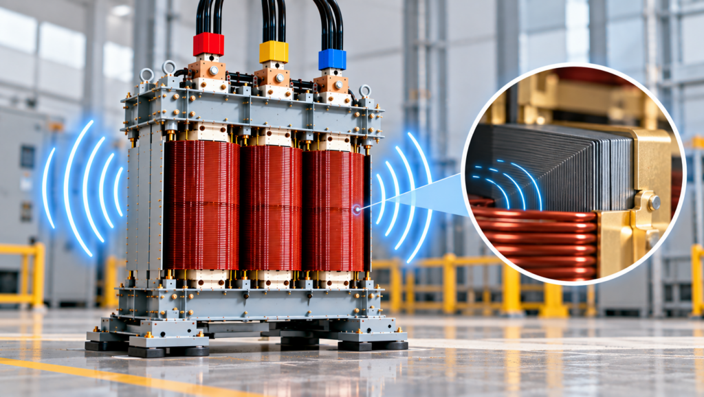
Its main source is magnetostriction. The electrical steel in the transformer core changes dimension slightly as magnetic flux passes through it. The dimensional change is microscopic, but the core repeats it continuously at power-system frequency. That movement creates vibration, which is transmitted through the core clamps, structural supports and enclosure as audible sound.
Magnetostrictive strain depends mainly on the magnitude of the magnetic field rather than its polarity. The steel therefore reaches a dimensional peak twice during each electrical cycle.
Fundamental core-vibration frequency ≈ 2 × electrical frequency
A transformer energized from a 60 hertz supply consequently produces a strong sound component around 120 hertz. On a 50 hertz system, the corresponding component is around 100 hertz. Magnetostriction is not perfectly sinusoidal, so higher-frequency components are normally present as well. Those components give transformer hum its characteristic layered tone rather than a single pure note.
This is why a steady low-frequency hum is not, by itself, evidence of a defect. The sound is a physical consequence of alternating magnetic excitation. The engineering objective is not to eliminate magnetostriction, which is impossible, but to control how strongly the resulting vibration is generated, transmitted and radiated.
Volts per Hertz Has a Direct Effect on Core Noise
Core sound is strongly influenced by magnetic flux density. For a given transformer design, core flux is approximately proportional to the applied voltage divided by frequency:
Core flux density ∝ voltage ÷ frequency
A transformer receiving excessive voltage operates at a higher flux density. The same effect occurs when frequency falls while voltage remains unchanged. Either condition increases volts per hertz and moves the core closer to magnetic saturation.
Magnetostrictive strain increases sharply as the core approaches saturation. The result can be a noticeable increase in sound even when the transformer is lightly loaded. This is one reason a louder hum should not automatically be attributed to load current.
The operating voltage, tap position and system frequency should be checked before mechanical corrective work begins. A tap selected for the wrong supply condition can unintentionally increase core excitation. Generator applications also require attention because voltage and frequency may vary more during starting, load transfer or transient operation than they do on a stiff utility supply.
A low-sound transformer design cannot compensate indefinitely for excessive volts per hertz. The magnetic operating point must remain within the design basis of the core.
Core Steel and Joint Construction Affect How Much Vibration Is Produced
Transformer cores are assembled from thin sheets of electrical steel. The laminations reduce eddy-current losses, but their material properties, cutting accuracy, stacking pattern and mechanical restraint also influence sound.
Low-loss grain-oriented steel allows the core to carry flux efficiently in the rolling direction. Material selection alone, however, does not determine the final sound level. Poorly formed joints can create local flux crowding. Uneven stacking can introduce mechanical gaps. Inadequate clamping allows components to move against one another.
Step-lap joint construction distributes flux transfer through the core joint more gradually than a simple butt joint. When the laminations are cut and assembled accurately, the arrangement reduces local magnetic disturbance and helps limit vibration at the joints.
Clamping presents a practical trade-off. The core must be restrained firmly enough to prevent movement, but the clamping system must not damage the laminations or create unintended electrical paths between them. Core hardware, support channels and enclosure connections must also avoid transferring more vibration than necessary into the outer structure.
A sharp buzz or metallic rattle is therefore different from normal magnetostrictive hum. It may indicate movement in a clamp, joint, panel or support rather than an increase in normal core sound.
Winding Noise Increases With Load
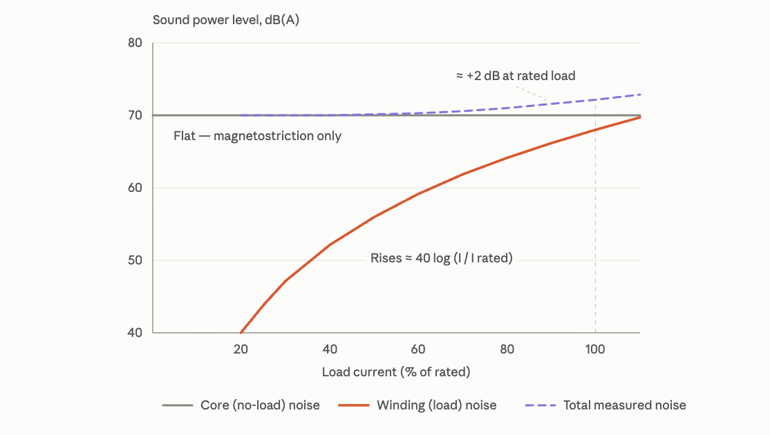
Core noise is present at no load. Winding noise develops as current flows.
Current in the primary and secondary windings produces electromagnetic forces between conductors. These forces vary through the electrical cycle and can cause microscopic movement within the winding assembly. Because electromagnetic force is related approximately to the square of current, winding forces can rise rapidly as loading increases.
A properly designed transformer restrains this movement through conductor geometry, spacers, blocking, bracing and insulation treatment. Under normal conditions, winding vibration remains controlled. The situation changes when the transformer is heavily loaded, mechanically damaged or exposed to a significant short-circuit event.
Short-circuit currents create forces far above normal operating levels. A transformer may remain electrically functional after a fault while experiencing movement within its winding-support system. A new load-dependent buzz following a short circuit deserves investigation even when insulation resistance and routine electrical measurements appear acceptable.
Vacuum pressure impregnation and related resin-treatment processes improve the mechanical integrity of a winding assembly by bonding conductors and insulation into a more rigid structure. They can reduce movement within the windings, but they do not eliminate magnetostriction in the core. The two noise sources must not be treated as the same problem. Our overview of VPI and VPE transformer construction provides more detail on how these insulation processes affect mechanical and dielectric performance.
Harmonics Can Change the Sound, but the Mechanism Matters
Non-linear loads are often blamed whenever a transformer becomes noisy. The connection is real, but it requires qualification.
The main core flux is established primarily by the applied voltage and frequency. Harmonic current drawn by a load does not automatically create an equivalent harmonic component in the main core flux. Current harmonics do, however, increase winding forces and produce stray magnetic flux in conductors, clamps, structural steel and enclosure components. These effects can introduce higher-frequency vibration and additional load noise.
Voltage distortion acts differently. Harmonic components in the applied voltage alter the core-flux waveform directly and can add magnetic excitation at additional frequencies. Whether load-current distortion produces meaningful voltage distortion depends partly on the impedance of the source and distribution system.
This distinction matters during troubleshooting. A current waveform with high total harmonic distortion does not, by itself, prove that the main core is being overexcited. Current, voltage, frequency, loading and sound should be evaluated together.
Where harmonic loading is substantial, the transformer must be designed for the resulting thermal and mechanical duty. A K-factor-rated transformer is designed to tolerate specified harmonic loading without excessive overheating. A harmonic-mitigating transformer uses winding arrangements and phase displacement to reduce selected harmonic currents in the wider system. Neither product should be selected solely as a general-purpose noise-control measure; the choice must be based on the electrical load profile.
Fans, Airflow and Enclosures Add Their Own Sound
Forced-air cooling introduces a separate noise source. Fan sound is generally broader and higher in frequency than core hum, making it easy to distinguish when the fans switch on.
Fan speed, blade design, motor condition and airflow resistance all affect the result. Restricted ventilation openings can produce turbulence, while dust accumulation or damaged bearings can create tonal or irregular noise. A transformer may therefore meet its natural-air sound requirement but become more noticeable when forced cooling operates.
The enclosure also acts as a radiator. Large sheet-metal panels can respond to internal vibration and produce a drum-like effect. Panel stiffness, fastening points, clearances and damping all affect how much sound reaches the room.
Adding acoustic material inside an enclosure is not automatically a safe correction. Any treatment must preserve dielectric clearances, flame-performance requirements and the airflow needed to control transformer temperature. Reducing noise by restricting cooling can create a more serious thermal problem.
Installation Can Amplify an Acceptable Transformer
Factory sound testing and installed room noise are related, but they are not interchangeable.
A factory test evaluates the transformer under defined conditions. The installed transformer becomes part of a much larger mechanical system that includes its base, floor, walls, conduits, bus connections, cable supports and surrounding equipment.
Two transmission paths are involved.
- Airborne sound travels directly from the core, coils, fans and enclosure into the room.
- Structure-borne vibration passes through the transformer base or connected services into the building. A wall, floor slab, ceiling or sheet-metal duct can then radiate that vibration over a larger surface area.
This is the issue that catches many installations. A transformer is placed on isolation pads, but rigid conduits bridge the isolation and carry vibration directly into the structure. In other cases, the pads are too stiff for the equipment weight and provide little meaningful isolation.
Isolation mounts must be selected for the transformer’s mass, centre of gravity, forcing frequency and required static deflection. Spring systems also need adequate lateral stability and restraint. Installing a generic rubber pad without checking these conditions may change the vibration path without materially reducing it.
Room geometry matters as well. Concrete surfaces, low ceilings and small reflective rooms can reinforce certain frequencies. Corners often make low-frequency sound more noticeable. Locating a transformer against a wall shared with an office, meeting room, studio or residential space can create an acoustic problem even when the electrical-room level appears reasonable.
Sound-sensitive applications must therefore be planned as equipment-and-building problems, not transformer-only problems.
A Change in Sound Should Be Investigated Systematically

A stable hum that has remained consistent with voltage, frequency and operating load is normally expected. A meaningful change deserves attention, but sound alone should not be used to diagnose an internal failure.
-
A Sudden Increase in the Existing Hum
When the basic tone remains similar but becomes substantially louder, check supply voltage, system frequency and tap position. Increased volts per hertz can raise core noise without a corresponding increase in load.
Loading, phase balance and fan operation should then be reviewed. Measurements taken before and after the sound change are more useful than a single reading.
-
A New Metallic Rattle or Sharp Buzz
This type of sound often points to a loose enclosure panel, mounting fastener, conduit support or external sheet-metal component. Accessible external hardware should be checked before assuming the noise comes from the core and coil assembly.
Internal clamps and winding supports should only be inspected under the manufacturer’s procedures and appropriate electrical-safety controls.
-
Noise That Appears After a Fault
A new sound following a short circuit, ground fault or protective-device operation may indicate that the winding or its support system experienced mechanical stress. The transformer should be evaluated in relation to the magnitude and duration of the fault rather than returned to service based only on a visual inspection.
-
Hissing, Crackling or Intermittent Snapping
These sounds are not part of normal transformer hum. They may be associated with contamination, tracking, arcing or discharge activity, although the sound by itself cannot identify the exact source.
When irregular noise is accompanied by overheating, smoke, odour, visible discharge or protective-device operation, the transformer should be de-energized and inspected by qualified personnel under the site’s established safety procedure.
Trending temperature, load, voltage, sound and vibration provides a better basis for diagnosis than relying on human memory. These checks can be incorporated into a structured transformer maintenance program.
Noise Control Begins With the Specification
Low sound is easier to engineer before manufacture than to correct after the transformer, conduits and building finishes are installed.
The transformer designer can control core flux density, core-steel grade, joint geometry, clamping, winding bracing, insulation treatment, internal supports, enclosure stiffness and cooling arrangement. These decisions involve trade-offs. A lower core flux density may reduce sound, but it generally requires more core material and can increase transformer dimensions, mass and cost.
The project specification should identify the actual acoustic requirement rather than relying on a general statement such as “low-noise transformer.” At minimum, the schedule should establish:
- The transformer type, kVA rating, voltage class and cooling mode.
- The applicable sound standard and required average sound level.
- Whether a sound level below the standard value is required.
- Whether the requirement applies under natural-air or forced-air operation.
- The proposed room location and adjacent sound-sensitive occupancies.
- Responsibility for vibration isolators, flexible connections and conduit support.
- Any field sound-testing requirement and the measurement conditions.
A special low-sound transformer will not correct an installation that rigidly couples it to the building. Conversely, extensive acoustic treatment may be unnecessary when the actual problem is an incorrect tap position or loose enclosure panel. The source and transmission path must be identified before the remedy is selected.
Which Sound Standard Applies?
The applicable standard depends on the transformer category, voltage class and market.
For general-application dry-type transformers in the United States, NEMA ST 20-2021, Dry Type Transformers for General Applications, is the relevant NEMA publication. The current edition applies to single-phase and polyphase dry-type transformers used to supply power, heating and lighting circuits.
For Canadian dry-type transformer performance, CSA C9:17 (R2022), Dry-Type Transformers, addresses standardized electrical and mechanical features and test procedures. Its current edition specifically notes the alignment of average audible sound levels with current industry practice.
CSA C22.2 No. 47-13 (R2023), Air-Cooled Transformers (Dry Type) serves a different purpose. It is a Canadian Electrical Code, Part II product-safety and conformity standard. Its scope states that performance requirements are addressed by CSA C9 where applicable. The two CSA standards should therefore not be treated as interchangeable.
NEMA TP 80050-2013 (R2024) is the current designation for the publication formerly known as NEMA TR 1. It covers audible sound levels for several transformer categories but excludes dry-type transformers covered by NEMA ST 20. A broad reference to “NEMA TR 1” is therefore not sufficient for a general-purpose dry-type transformer specification.
The exact permitted sound value should be taken from the table that applies to the transformer’s rating, construction and cooling class. A general range such as 55–65 dBA may provide rough context, but it should not be used as the acceptance criterion for every 500–1000 kVA transformer.
Conclusion
Transformer hum begins with magnetostriction in the core, but the sound heard in an operating facility is rarely produced by one mechanism alone. Core flux density determines the basic no-load excitation. Winding current adds load-dependent mechanical forces. Harmonics can introduce higher-frequency winding and stray-flux effects. Fans, enclosure panels, mounting hardware and the building structure determine how those vibrations reach occupied spaces.
The practical distinction is between sound generation and sound transmission. Core design, winding construction and cooling selection control what the transformer produces. Mounting, flexible connections, conduit support and room acoustics control how strongly the installation reproduces it.
A low-sound requirement should therefore be specified with the applicable standard, operating mode and installation conditions defined. When an existing transformer changes sound, voltage, frequency, loading and external mechanical paths should be checked before the noise is treated as evidence of an internal defect.