Low-Ambient Temperature Considerations for Dry-Type Transformers
Dry-type transformers are frequently installed in regions where ambient temperatures may fall to –40 °C or lower. In such environments, reliable performance depends not only on the transformer’s rated operating ambient, but on proper handling during storage and disciplined energization practices during cold start.
Three distinct conditions must be clearly differentiated:
- Storage (de-energized condition)
- Cold-start energization below 0 °C
- Continuous operation at low ambient once energized
Each condition introduces different mechanical, thermal, and dielectric stresses. Improper storage or uncontrolled energization at sub-freezing temperatures can lead to insulation damage that may not be immediately apparent, but can significantly reduce long-term transformer reliability.
This paper consolidates Rex guidance from product manuals and technical references to provide a unified engineering framework for low-ambient applications.
Storage Conditions and Environmental Control
Any transformer not installed and energized immediately should be stored in a dry, clean environment with uniform temperature conditions to prevent condensation on windings and internal components. A heated building with adequate air circulation is preferred. The storage area should be protected from cement dust, plaster, paint, dirt, water intrusion, corrosive gases, and airborne contaminants. The floor should resist upward migration of water vapor, and the location must be free from roof leaks or moisture intrusion pathways.
The primary objective during storage is moisture control. Temperature alone does not typically damage a de-energized transformer; however, temperature cycling around the freezing point can promote condensation within the enclosure. Moisture accumulation on windings, core laminations, clamping systems, or bus connections introduces significant dielectric risk at energization.
When transformers are stored at or near freezing, condensation can be greatly reduced by maintaining the enclosure temperature approximately 5 °C to 10 °C above ambient. This may be achieved through installation and energization of space heaters. However, anti-condensation heaters supplied with the transformer are generally intended to reduce moisture accumulation and may not be sufficient to maintain the enclosure above minimum recommended storage temperature limits. Where necessary, additional internal or external heaters may be required.
When heaters are used during storage, ventilation openings may be temporarily blocked or covered to retain heat within the enclosure. A minimum clearance must remain to allow moist air to escape, and all coverings must be removed prior to energization to restore normal ventilation. Heating devices must never come into direct contact with transformer coil insulation.
Outdoor storage is not recommended. If unavoidable, the unit must remain protected with its original plastic wrapping, supplemented by suitable desiccant materials such as silica gel packs. The transformer should be periodically inspected for signs of condensation on windings, support blocks, core assemblies, and bus structures.
Before placing any stored transformer into operation, insulation resistance testing shall be performed. If readings are below recommended values, or if visible condensation is present, a controlled drying procedure is required prior to energization.
Transformers stored at sub-freezing temperatures must be allowed to thermally stabilize above freezing before energization.
Storage Temperature Limits by Transformer Design
Storage temperature limits apply only when the transformer is not energized.
For VPI and VPE dry-type transformers, the recommended minimum storage temperature is down to –50 °C, provided the unit remains dry, protected from moisture ingress, and not subjected to mechanical shock while cold.
These insulation systems do not experience electrical or magnetic stress during storage. The primary risks are moisture ingress, condensation during temperature cycling, and mechanical damage when insulation materials are less flexible at low temperature.
For cast coil transformers, the recommended minimum storage temperature is –20 °C . Below this temperature, epoxy resin systems become increasingly brittle. While dielectric strength may remain intact, impact resistance decreases, increasing the risk of micro-cracking or long-term dielectric degradation, particularly if mechanical shock occurs.
Accordingly, storage of cast coil transformers below –20 °C is not recommended unless specifically approved and accompanied by controlled protective measures.
The distinction between VPI/VPE and cast coil during storage is primarily mechanical rather than electrical.
Continuous Operation at Low Ambient
Operating ambient temperature refers to continuous service while the transformer is energized and supplying load.
For both VPI/VPE and cast coil transformers, the typical minimum operating ambient is –30 °C however for special applications, VPI/VPE transformer can be designed with a minimum operating ambient as low as –40 °C
Low ambient temperatures do not inherently impair electrical performance once the transformer is energized. No-load losses generate sufficient heat to maintain appropriate internal conditions, even in ambient temperatures as low as –30 °C. Insulation systems remain electrically stable provided mechanical integrity is intact and moisture is controlled.
In steady state, internal winding temperature is governed primarily by load current and transformer temperature rise design. The principal limitation at low temperature is not continuous operation, but the energization of a cold transformer.

Cold-Start Energization Below 0 °C
Cold-start energization presents the highest risk condition for dry-type transformers in cold climates.
Two primary mechanisms must be addressed:
First, coil insulation systems become mechanically stiff at low temperatures. During energization and subsequent loading, copper conductors expand as temperature rises. If expansion occurs more rapidly than insulation can accommodate, cracking between turns or layers may occur, potentially leading to internal faults.
Second, low ambient temperatures promote condensation formation inside the enclosure and on coil surfaces. Energizing a transformer with moisture present on windings can result in dielectric breakdown and insulation damage.
To mitigate these risks, energizing a transformer below 0 °C requires a controlled cold-start procedure.
Cold-Start Procedure Requirements
If coil temperature is below –20 °C, the transformer must first be warmed to –20 °C or higher using external heat. Ventilation openings may be partially blocked to accelerate warming, provided sufficient clearance remains to allow moist air to escape. Direct heat contact with coil insulation is strictly prohibited.
Once above –20 °C, recommended pre-service tests, including insulation resistance (megger) testing, must be performed. If insulation resistance readings fall below acceptable values, additional heating shall be applied for a minimum of 12 hours, followed by re-testing. This cycle shall be repeated until readings meet specification.
After acceptable insulation resistance values are confirmed, the transformer may be energized at no load and allowed to warm for approximately 24 hours, or until winding temperature reaches at least 0 °C. External heat and partial ventilation blockage may remain in place during this warm-up period.
Once winding temperature exceeds 0 °C, temporary heating and ventilation restrictions may be removed, and the transformer may be loaded as appropriate.
This staged energization process ensures that conductors do not expand more rapidly than insulation systems can accommodate and that all internal moisture has been removed prior to loading.
Engineering Implications for Specification
In cold-climate projects, specifications often reference only the minimum operating ambient, such as –40 °C. While technically correct for energized operation, this does not address storage exposure or cold-start requirements.
Proper project documentation should define:
- Minimum storage temperature by transformer design
- Environmental storage requirements and moisture control provisions
- Mandatory insulation resistance testing prior to energization
- Controlled cold-start procedure below 0 °C
- Heater requirements for outdoor or intermittently energized installations
Reliability in cold climates is not achieved solely by selecting a –40 °C rated transformer. It depends equally on storage discipline, moisture control, staged energization, and commissioning planning.
Conclusion
Dry-type transformers operate reliably in ambient temperatures as low as –30°C once energized and thermally stabilized. VPI/VPE designs tolerate storage down to –50 °C when properly protected, while cast coil designs should not be stored below –20 °C without special approval.
The most critical condition is energization below 0 °C. Controlled heating, insulation resistance verification, staged no-load warm-up, and careful ventilation management are essential to prevent insulation cracking and moisture-related failures.
In low-ambient applications, long-term reliability is determined less by steady-state temperature rating and more by disciplined storage and commissioning practices. Proper environmental control and adherence to cold-start procedures ensure insulation integrity and sustained transformer performance throughout its service life.
Short-Circuit Withstand Capability of Dry Type Transformers
In dry type transformer design, thermal performance often receives the most attention. However, from a reliability and system protection perspective, short-circuit withstand capability is frequently the more critical parameter.
Transformers rarely fail under steady-state loading. They fail during faults.
A downstream short circuit subjects the transformer to extremely high currents within milliseconds. Those currents generate intense mechanical forces in the windings. If the transformer is not mechanically designed to withstand those forces, permanent deformation, insulation damage, or catastrophic failure can occur — even if the unit is thermally adequate for its rating.
This article examines how short-circuit forces develop in dry type transformers, what governs mechanical withstand capability, and what engineers should evaluate during specification.
Fault Current and Mechanical Force
When a secondary fault occurs, the transformer delivers current limited primarily by its impedance and the upstream source impedance. The initial symmetrical short-circuit current can be approximated as:
Isc= IFL / Zpu
Where IFL is full-load current and Zpu is transformer per-unit impedance.
For a transformer with 5.75% impedance:
Isc≈1/0.0575≈17.4 puI
This means approximately 17 times rated current under symmetrical conditions. The first-cycle peak current may reach approximately 2.6 times the symmetrical RMS value due to DC offset.
The critical point is that mechanical force is proportional to the square of the current:
F ∝ I2F
A 17× increase in current produces nearly 300× the mechanical force compared to normal operating conditions. This is fundamentally a mechanical shock event, not a thermal one.
Nature of Forces Inside the Transformer
Short-circuit forces act in two principal directions: radially and axially.
Radial forces develop between concentric windings. These forces create hoop stress that tends to expand or compress the coils. In cast resin transformers, excessive radial stress can lead to cracking of the encapsulation or permanent deformation of the winding.
Axial forces act along the vertical axis of the windings due to leakage flux interactions. These forces can compress winding sections together or drive them apart, potentially causing spacer displacement or turn movement.
In oil-filled transformers, the insulating liquid provides some damping and hydrostatic support. Dry type transformers do not have this benefit. Their mechanical integrity depends entirely on conductor geometry, resin bonding (in VPI/VPE designs), epoxy encapsulation (in cast resin designs), axial clamping pressure, and the rigidity of the core and frame assembly.
Standards and Qualification
Short-circuit withstand capability for dry type transformers is addressed in:
- IEEE C57.12.01 (General Requirements for Dry Type Transformers)
- IEEE C57.12.91 (Test Code)
- IEC 60076-5 (Ability to Withstand Short Circuit)
These standards define the mechanical duty the transformer must survive without permanent deformation or insulation failure. Not all transformers are individually short-circuit tested; many designs are validated by similarity to previously tested units.
For critical installations or locations with high available fault current, engineers may request documented short-circuit test data to confirm design robustness.
Impedance as a Mechanical Design Variable
Transformer impedance is often selected based on voltage drop and coordination studies. However, it directly controls short-circuit forces.
Because fault current is inversely proportional to impedance and force scales with the square of current, small impedance reductions produce disproportionately large increases in mechanical stress.
For example, reducing impedance from 6% to 4% increases symmetrical fault current from roughly 16.7 pu to 25 pu. The corresponding mechanical force more than doubles.
This trade-off is frequently overlooked during value engineering exercises. Lower impedance improves voltage regulation but significantly increases mechanical stress during faults. In facilities with high available fault current, impedance selection should be evaluated from both system and mechanical perspectives.
Mechanical Design Considerations in Dry Type Units
Short-circuit performance in dry type transformers depends on structural integrity of the windings and support system. Robust designs typically incorporate rigid conductor arrangements, controlled axial clamping pressure, reinforced spacer systems, and mechanically stable resin systems that resist cracking under transient stress.
In cast resin transformers, epoxy formulation and curing control influence long-term crack resistance. In VPI or VPE designs, the bond between conductor and insulation system is critical to prevent movement under high electromagnetic forces.
The mechanical rigidity that makes dry type transformers attractive for indoor and environmentally sensitive installations also means that internal stress must be carefully managed during fault events.
Repeated Fault Exposure and Latent Damage
Standards assume a defined short-circuit event. In practice, transformers may experience multiple downstream faults, motor-related transients, or protection mis-coordination.
Even when a transformer appears to “survive” a fault, internal winding displacement can initiate insulation degradation that manifests months later as partial discharge activity, increased audible noise, or localized overheating.
For medium and large kVA installations, post-fault testing such as insulation resistance measurement, turns ratio verification, and partial discharge assessment may be warranted before returning the unit to full service.
Practical Specification Guidance
When applying dry type transformers in systems with substantial available fault current, short-circuit capability should be treated as a core design parameter rather than a compliance checkbox.
At minimum, the specifying engineer should verify the available fault current at the installation point, confirm the selected impedance supports both system coordination and mechanical durability, and ensure compliance with IEEE C57 short-circuit requirements. In mission-critical facilities such as data centers or industrial plants, documented short-circuit test validation may be appropriate.
Avoid reducing impedance solely to improve voltage drop performance without evaluating the mechanical implications.
Thermal Rating vs. Mechanical Withstand
Thermal overload capability and short-circuit withstand capability address different failure modes.
Thermal design protects the transformer from insulation aging due to elevated temperature. Short-circuit design protects the transformer from instantaneous mechanical destruction.
A transformer may be thermally robust yet mechanically vulnerable during a high-magnitude fault. Both aspects must be considered in responsible engineering practice.
Conclusion
Short-circuit withstand capability in dry type transformers is fundamentally a mechanical design issue driven by system fault current and transformer impedance.
Because fault forces scale with the square of current, even modest impedance changes can dramatically alter internal stress levels. In dry type construction — where rigid windings replace oil-supported structures — axial clamping, conductor design, resin integrity, and structural bracing determine whether the unit maintains internal alignment after a fault.
Short-circuit performance must be evaluated during specification, not after a failure investigation.
Mechanical integrity under fault conditions is not an optional attribute. It is a defining element of transformer reliability in real-world power systems.
Transformer Turns Ratio: Formula, Meaning, and How to Use It
The turns ratio is one of the most fundamental concepts in transformer design and operation. It defines how voltage is transformed from primary to secondary and determines how current levels change accordingly.
Engineers, electricians, and students frequently search for the turns ratio of a transformer formula, or ask what the turn ratio of a transformer actually means in practical terms. Understanding the turns ratio of transformer windings is essential for voltage selection, fault calculations, impedance studies, and system design.
This article explains the turns ratio, presents the governing formula, and shows how it is used in real-world transformer applications.
What Is the Turns Ratio of a Transformer?
The turns ratio describes the relationship between the number of turns in the primary winding and the number of turns in the secondary winding.
In simple terms:
- More turns on a winding produce higher voltage
- Fewer turns produce lower voltage
The transformer does not “create” voltage — it changes voltage in proportion to the number of winding turns.
Turns Ratio of a Transformer Formula
The fundamental turns ratio of a transformer formula is:
Where:
Vp = Primary voltage
Vs = Secondary voltage
Np = Number of primary turns
Ns = Number of secondary turns
This formula shows that voltage ratio is directly proportional to turns ratio.
It can also be written as:

Example: Step-Down Transformer
A transformer rated:
- 480 V primary
- 120 V secondary
Using the formula:

This means the primary has four times as many turns as the secondary.
Turns ratio = 4:1
Voltage is reduced by a factor of four.
Example: Step-Up Transformer
A transformer rated:
- 208 V primary
- 600 V secondary

The secondary has approximately 2.88 times more turns than the primary.
Turns ratio ≈ 1:2.88
Relationship Between Turns Ratio and Current
While voltage is proportional to turns ratio, current behaves inversely.

If voltage increases, current decreases proportionally (ignoring losses). This is why transformers can step voltage up for transmission and reduce current, minimizing conductor losses.
Turns Ratio in Three-Phase Transformers
In three-phase transformers, the turns ratio still applies to each individual phase winding. However, line-to-line voltages depend on winding configuration (delta or wye).
For example:
- In a wye connection, line voltage = phase voltage × √3
- In a delta connection, line voltage = phase voltage
Therefore, when determining the turns ratio of transformer windings in three-phase systems, engineers must consider phase configuration carefully.
How to Use the Turns Ratio in Practice
Understanding the turn ratio of a transformer is useful for:
- Verifying nameplate voltage relationships
- Troubleshooting incorrect output voltage
- Confirming proper transformer connections
- Calculating reflected impedance
- Evaluating fault current
- Performing transformer testing
Turns ratio testing (TTR testing) is commonly used during commissioning to confirm winding integrity and correct connection.
Turns Ratio and Impedance Reflection
One important application of turns ratio is impedance reflection. Impedance seen from one side of the transformer reflects according to:

This squared relationship is critical in:
- Fault current studies
- Protection coordination
- System modeling
Small changes in turns ratio can significantly affect reflected impedance.
Turns Ratio and Tap Changers
Transformer taps adjust the effective number of turns in a winding. When a tap position is changed:
- The turns ratio changes
- The secondary voltage changes proportionally
For example, a +2.5% tap effectively increases primary turns relative to secondary, adjusting output voltage.
Common Misunderstandings About Turns Ratio
Several common misconceptions exist:
- Turns ratio is not the same as impedance percentage
- It does not directly determine kVA rating
- It does not change transformer efficiency
- It applies to phase windings, not always directly to line voltage
Understanding these distinctions prevents design errors.
Turns Ratio in Transformer Testing
During manufacturing and commissioning, turns ratio tests verify:
- Correct winding connections
- Proper tap position
- No shorted turns
- Accurate voltage ratio
Any deviation from expected turns ratio may indicate winding damage or connection errors.
Conclusion
The turns ratio of transformer windings defines the fundamental relationship between voltage and current in power systems. By applying the turns ratio of a transformer formula, engineers can determine voltage transformation, reflected impedance, and system behavior under load and fault conditions.
Understanding the turn ratio of a transformer is essential for proper sizing, troubleshooting, testing, and protection coordination. When applied correctly, it provides a powerful and practical tool for electrical system design.
Transformer Grounding and Bonding Explained: Key Principles
Proper grounding and bonding are fundamental to the safe and reliable operation of transformer installations. Although the terms are often used interchangeably, grounding and bonding serve distinct functions within an electrical system. When implemented correctly, they control fault current, stabilize voltage, improve surge protection performance, and protect personnel. When implemented incorrectly, they can lead to nuisance tripping, equipment damage, insulation stress, or serious safety hazards.
Understanding transformer grounding and bonding is therefore essential for engineers, electricians, and facility managers involved in system design and installation. This article explains the underlying principles, common grounding methods, and practical considerations that apply to transformer-based systems.
Grounding vs. Bonding: Clarifying the Difference
Grounding and bonding perform different but complementary roles.
Grounding establishes a deliberate connection between part of the electrical system and earth. Its primary purpose is to stabilize system voltage relative to ground and to provide a reference point that limits overvoltage during lightning events or line-to-ground faults.
Bonding, by contrast, connects metallic components together to ensure they remain at the same electrical potential. The goal of bonding is safety — minimizing touch voltage and ensuring that fault current returns effectively to the source so that protective devices can operate quickly.
In a transformer installation, grounding defines the system reference. Bonding ensures all conductive parts behave as one continuous, low-impedance path during a fault.
Why Transformer Grounding Is Required
When a transformer secondary supplies a new distribution system, it often creates what is known as a separately derived system. In these cases, the transformer neutral becomes the reference point for that system and must be intentionally grounded.
Grounding the transformer secondary serves several purposes. It establishes a stable voltage reference, allows ground-fault current to return to the source in a controlled manner, and ensures that overcurrent protection devices operate as intended. Without a defined grounding point, the system can “float”, meaning its voltage relative to earth may shift unpredictably under fault or surge conditions. This floating condition increases insulation stress and can expose equipment to damaging overvoltages.
Common Grounding Methods for Transformers
The method chosen to ground a transformer significantly affects system behavior during faults.
In a solidly grounded system, the transformer neutral is directly connected to earth. This configuration produces relatively high ground-fault current, which allows protective devices to operate quickly and decisively. It is widely used in commercial and institutional power systems where rapid fault clearing is desirable.
Resistance grounding introduces a resistor between the transformer neutral and ground. This limits ground-fault current to a controlled level, reducing equipment damage and arc-flash energy. In industrial environments, resistance grounding often provides a balance between protection sensitivity and equipment survivability.
High-resistance grounding further reduces fault current to very low levels, sometimes only a few amperes. This allows continued system operation during a single line-to-ground fault, provided detection systems are in place. While this approach reduces arc-flash hazard, it requires careful monitoring and maintenance.
Ungrounded systems, although historically used, are less common in modern installations due to the increased risk of transient overvoltages and difficulty detecting ground faults.
Bonding in Transformer Installations
Bonding ensures that exposed conductive parts remain at equal potential, minimizing shock risk and ensuring effective fault clearing. In a transformer installation, this includes bonding the transformer enclosure, core, and metallic components to the equipment grounding conductor.
For dry-type transformers, bonding practices are particularly important. The transformer enclosure must be securely connected to the grounding system. If the secondary is a separately derived system, the neutral-to-ground bond must be made at one location only. Multiple neutral bonds downstream can create circulating currents, leading to overheating, nuisance tripping, and inaccurate protection performance.
A properly bonded system ensures that fault current flows along a predictable, low-impedance path back to the source.
Grounding and Fault Current Behavior
The chosen grounding method directly affects ground-fault current magnitude. A solidly grounded transformer allows high fault current to flow, enabling fast protective device operation. A resistance-grounded system limits that current, reducing mechanical and thermal stress on equipment.
These differences influence breaker selection, arc-flash calculations, and overall protection coordination. Grounding decisions must therefore be made with consideration of both safety and operational objectives.
Grounding and Surge Protection
Transformer grounding also plays a major role in surge protection performance. Surge arresters rely on a low-impedance path to ground in order to divert lightning or switching surges safely. If grounding conductors are long, undersized, or poorly connected, the effectiveness of surge arresters can be significantly reduced.
A well-designed grounding system minimizes residual voltage during transient events and helps protect transformer insulation from damage.
Code Compliance Considerations
Transformer grounding and bonding must comply with the applicable electrical code and local authority requirements. In Canada, installations are governed by the Canadian Electrical Code (CEC). In the United States, grounding and bonding practices must meet the requirements of the National Electrical Code (NEC).
Because grounding affects both safety and protection performance, compliance is not optional. Proper documentation and adherence to code requirements are essential components of transformer installation.
Conclusion
Transformer grounding and bonding are foundational to safe and stable power system operation. Grounding establishes a defined voltage reference and controls fault behavior, while bonding ensures metallic components remain at equal potential and that protective devices operate correctly.
By understanding grounding methods, their impact on fault current, and the importance of proper bonding, engineers and electricians can design and install transformer systems that perform safely and reliably for decades
The Role of Transformers in Energy Efficiency and Power Loss Reduction
Transformers operate continuously in most electrical systems, often for decades at a time. Although they contain no moving parts, their impact on overall energy efficiency is significant. Even small improvements in transformer performance can translate into measurable reductions in energy consumption, operating costs, and greenhouse gas emissions over the life of an installation.
Understanding how transformers influence energy efficiency requires examining the sources of transformer losses, how those losses are managed through design, and how proper specification contributes to long-term power loss reduction. This article explores the role of transformers in system efficiency and explains how design decisions directly affect real-world performance.
Understanding Transformer Losses
Transformer losses fall into two primary categories: no-load losses and load losses. Both affect energy efficiency, but they behave differently.
No-load losses (also called core losses) occur whenever the transformer is energized, regardless of whether it is supplying load. These losses result from hysteresis and eddy currents in the magnetic core. Because they are constant, no-load losses accumulate continuously throughout the transformer’s operating life.
Load losses, sometimes referred to as conductor losses, occur only when current flows through the windings. These losses increase with the square of the load current and are therefore highest when the transformer operates near full capacity. Additional stray losses caused by leakage flux and harmonic currents also contribute to total load losses.
Efficiency is maximized when the transformer is designed so that the balance between no-load and load losses matches its expected duty cycle.

Efficiency and Transformer Design
Transformer efficiency is defined as the ratio of output power to input power. Modern dry-type transformers commonly achieve efficiencies above 98%, but even small improvements in loss performance can yield meaningful long-term savings.
Design factors influencing efficiency include:
- Core material selection and lamination quality
- Conductor sizing and geometry
- Winding configuration
- Cooling design
- Impedance selection
For example, increasing conductor cross-sectional area reduces winding resistance and load losses but increases initial material cost. Likewise, higher-grade core steel reduces hysteresis losses but affects overall transformer size and manufacturing complexity.
Engineering a transformer for efficiency involves optimizing these competing variables for the intended operating profile.
Load Profile and Real-World Efficiency
A transformer rarely operates continuously at full load. Many commercial and institutional transformers operate at 30–60% of rated capacity for extended periods.
In lightly loaded applications, no-load losses may dominate total losses. In heavily loaded systems, load losses become the primary contributor. Therefore, proper transformer sizing plays a critical role in energy efficiency.
Oversizing a transformer may increase no-load losses unnecessarily. Undersizing increases load losses and thermal stress. Correct kVA selection, based on realistic load analysis, improves long-term efficiency and reliability.
Harmonics and Their Impact on Losses
In modern facilities with non-linear loads—such as VFDs, LED lighting, and data processing equipment—harmonic currents increase transformer heating and stray losses.
Harmonics can:
- Increase conductor losses
- Raise eddy current losses
- Elevate operating temperature
- Reduce effective efficiency
Design strategies such as K-rated transformers, harmonic mitigating designs, or appropriately sized conductors help control these additional losses and maintain energy efficiency under real-world operating conditions.
Temperature Rise and Insulation Life
Transformer efficiency is closely tied to operating temperature. Higher losses produce higher temperatures, which accelerate insulation aging and reduce service life.
Using higher-temperature insulation systems while designing for lower operating temperature rise can improve longevity and efficiency stability over time. This approach provides thermal margin for elevated ambient temperatures, harmonics, and future load growth without compromising performance.
In dry-type transformers, careful airflow management and proper cooling classification (AN/ANN or AF/AFN) also influence thermal efficiency.
Regulatory and Efficiency Standards
Minimum efficiency requirements for transformers are established by regulatory bodies. In Canada, Natural Resources Canada (NRCan) sets minimum efficiency standards for many distribution transformer classes. These regulations ensure baseline performance but do not necessarily represent optimized lifecycle efficiency.
Specifying transformers solely to minimum compliance may not yield the lowest lifetime operating cost. Evaluating total ownership cost—including energy losses over the transformer’s life—often supports selecting higher-efficiency designs.
Power Loss Reduction Through System Design
Beyond transformer construction itself, system-level decisions also affect overall efficiency.
These include:
- Selecting appropriate impedance to balance voltage drop and loss
- Proper tap setting to maintain nominal voltage
- Avoiding unnecessary oversizing
- Coordinating protection to prevent overheating events
- Ensuring proper ventilation and installation conditions
Energy efficiency is not determined solely by transformer nameplate performance—it depends on correct application.
Dry-Type Transformer Considerations
Dry-type transformers, particularly VPI/VPE and cast coil designs, offer opportunities for optimized efficiency in commercial and industrial installations. Careful coil design, vacuum pressure impregnation processes, and high-grade core materials contribute to stable performance and reduced losses.
Selecting the appropriate dry-type design for the environment ensures that efficiency gains are not offset by temperature-related degradation or harmonic stress.
Long-Term Financial and Environmental Impact
Because transformers operate continuously, their cumulative losses over 20–30 years often exceed their initial purchase cost in energy value. Even a modest reduction in losses can result in significant energy savings over the life of the equipment.
From an environmental perspective, reducing transformer losses contributes directly to lower overall energy demand and reduced emissions associated with power generation.
Transformer efficiency is therefore both a financial and sustainability consideration.
Conclusion
Transformers play a critical role in energy efficiency within electrical power systems. Through careful design, proper sizing, and thoughtful application, both no-load and load losses can be minimized, improving long-term performance and reducing operating costs.
Energy efficiency is not merely a regulatory requirement—it is a design objective. When transformers are specified and applied correctly, they become an essential component of sustainable and cost-effective power system operation.
Lightning and Surge Protection for Transformers: Arresters & Coordination
Transformers are designed to operate reliably for decades, but their insulation systems are vulnerable to short-duration overvoltages caused by lightning strikes and switching events. These transient surges, though brief, can impose stresses far above normal operating levels and progressively weaken insulation, eventually leading to failure.
Effective lightning and surge protection is therefore an essential part of transformer application design. It relies on properly selected surge arresters, correct insulation coordination, appropriate grounding practices, and careful installation. This article explains the fundamentals of transformer surge protection, with particular attention to arrester selection, grounding considerations, and the voltage ratings that define arrester performance.
Sources of Surges Affecting Transformers
Transformers are exposed to overvoltages from both external and internal system events.
Lightning-induced surges are typically the most severe. A direct strike to an overhead line, or even a nearby strike, can generate steep-front voltage waves that travel along conductors toward transformers. These surges rise extremely fast and can stress insulation unevenly, particularly at winding ends and terminals.
Switching surges are more frequent but generally lower in magnitude. They occur during breaker operations, fault clearing, capacitor switching, or system reconfiguration. Over time, repeated switching surges can contribute to cumulative insulation aging if not properly controlled.
Why Transformers Require Surge Protection
Transformer insulation is designed for a specific combination of operating voltage, temporary overvoltage, and impulse withstand. Surge waveforms challenge this design because:
- Voltage rises occur much faster than insulation can redistribute stress
- End turns, and terminal regions experience concentrated electric fields
- Internal insulation may see partial discharge even when failure does not occur
Without adequate protection, even non-catastrophic surges can shorten transformer life.
Surge Arresters and Their Role
Surge arresters are the primary devices used to protect transformers from overvoltages. Modern systems use metal-oxide varistor (MOV) arresters, which behave as non-linear resistors.
Under normal operating voltage, an arrester remains essentially non-conductive. When surge voltage exceeds its threshold, the arrester conducts heavily and diverts surge energy to ground, limiting the voltage applied to transformer insulation.
Once the surge subsides, the arrester returns to its high-resistance state.
Understanding the Two Voltage Ratings on a Surge Arrester
Two voltage values are always associated with a surge arrester, and both are critical to correct selection.
Maximum Continuous Operating Voltage (MCOV) is the highest RMS voltage that can be applied continuously without damaging the arrester. MCOV must be greater than the system’s maximum steady-state phase-to-ground voltage, including allowances for system unbalance and temporary overvoltage.
Rated voltage is higher than MCOV and reflects the arrester’s ability to withstand short-duration overvoltages. It is used for classification and coordination but is not the voltage the arrester can tolerate continuously.
In practice, MCOV is selected first, and the rated voltage follows from that selection.
How System Grounding Affects Arrester Selection
System grounding has a direct impact on arrester voltage requirements. During a ground fault, the phase-to-ground voltage on unfaulted phases depends entirely on how the system neutral is grounded.
- Solidly grounded systems limit voltage rise and allow lower MCOV values
- Low-resistance grounded systems experience moderate voltage rise
- High-impedance grounded or ungrounded systems can see phase-to-ground voltage approach line-to-line voltage
As grounding becomes less effective, the arrester must tolerate higher continuous and temporary voltages.
The table below illustrates how grounding method directly influences typical arrester nominal voltage and MCOV selection for common North American system voltages.
| System Voltage
(kV L-L) |
Solidly Grounded
Nominal / MCOV (kV) |
Low-Resistance Grounded
Nominal / MCOV (kV) |
High-Resistance Grounded
Nominal / MCOV (kV) |
|---|---|---|---|
| 2.40 | 3 / 2.55 | 3 / 2.55 | 3 / 2.55 |
| 4.16 | 3 / 2.55 | 6 / 5.10 | 6 / 5.10 |
| 4.80 | 6 / 5.10 | 6 / 5.10 | 6 / 5.10 |
| 6.90 | 6 / 5.10 | 6 / 5.10 | 9 / 7.65 |
| 8.30 | 6 / 5.10 | 9 / 7.65 | 9 / 7.65 |
| 11.30 | 9 / 7.65 | 10 / 8.40 | 15 / 12.70 |
| 12.47 | 9 / 7.65 | 10 / 8.40 | 15 / 12.70 |
| 13.20 | 10 / 8.40 | 12 / 10.20 | 15 / 12.70 |
| 13.80 | 10 / 8.40 | 12 / 10.20 | 15 / 12.70 |
| 24.95 | 18 / 15.30 | 21 / 17.00 | 27 / 22.50 |
| 34.50 | 27 / 22.00 | 30 / 24.40 | 39 / 31.50 |
| 44.00 | 36 / 29.00 | 36 / 29.00 | 48 / 36.50 |
| 46.00 | 36 / 29.00 | 39 / 31.50 | 54 / 42/00 |
Key insight: as grounding effectiveness decreases, MCOV must increase to ensure arrester survivability—often at the expense of reduced protective margin.
Insulation Coordination with Transformers
Surge protection must be coordinated with transformer insulation strength. Transformer Basic Insulation Level (BIL) defines the maximum impulse voltage the insulation can withstand.
Proper insulation coordination ensures:
- Arrester clamping voltage remains below transformer BIL
- Adequate margin exists for aging, tolerances, and lead effects
- Surge energy is diverted before insulation breakdown occurs
Incorrect arrester selection can defeat insulation coordination even when arresters are installed.
Grounding and Installation Practices
An arrester can only protect effectively if it has a low-impedance path to ground. Long or poorly routed leads increase inductive voltage rise during fast surges.
Good practice includes:
- Installing arresters as close as possible to transformer terminals
- Using short, straight line and ground leads
- Bonding transformer tanks, arresters, and grounding systems
Grounding quality often determines whether surge protection succeeds or fails.
Surge Protection for Dry-Type Transformers
Dry-type transformers are often installed indoors but may still be exposed to surges through overhead feeders, outdoor substations, or long cable runs. VPI/VPE designs and cast coil transformers both require proper arrester coordination and grounding to prevent internal insulation stress.
Conclusion
Lightning and switching surges pose a serious risk to transformer insulation, but effective protection is achievable through proper arrester selection, grounding, and insulation coordination. Understanding how grounding affects MCOV requirements—and how arrester voltages relate to transformer BIL—is essential for reliable transformer protection.
When surge arresters, grounding practices, and transformer insulation are correctly coordinated, transformers can operate safely and reliably even in surge-prone environments.
What Is an Autotransformer? Simple Explanation, Diagram, and Uses
Autotransformers are widely used in electrical power systems, yet they are often misunderstood or confused with conventional isolation transformers. While both devices change voltage levels, an autotransformer does so using a simpler construction that offers advantages in size, efficiency, and cost—along with important limitations.
This article provides a straightforward explanation of what an autotransformer is, how it works, how it differs from an isolation transformer, and where it is most commonly used. A simple diagram is included to illustrate the basic concept.
What Is an Autotransformer?
An autotransformer is a transformer that uses a single continuous winding to perform voltage transformation. Unlike an isolation transformer, which has separate primary and secondary windings, an autotransformer shares part of the same winding between the input and output.
Voltage is changed by tapping the winding at different points. Depending on where the output is taken, the autotransformer can either step voltage up or step it down.
Because part of the winding is common to both sides, power is transferred both magnetically and electrically, which makes autotransformers more compact and efficient than isolation transformers.
How an Autotransformer Works
When voltage is applied to the full winding, a magnetic field is established in the core, just as in a conventional transformer. A portion of that winding is tapped to provide the desired output voltage.
Some of the power is transferred by transformer action (through the magnetic field), while the rest flows directly through the shared winding. This shared path is what reduces material requirements and losses—but it also means there is no electrical isolation between input and output.
Autotransformers can operate as:
- Step-down transformers, reducing voltage
- Step-up transformers, increasing voltage
- Buck-boost transformers, making small voltage corrections
- Simple Autotransformer Diagram (Conceptual)
Below is a simplified conceptual representation of an autotransformer winding:
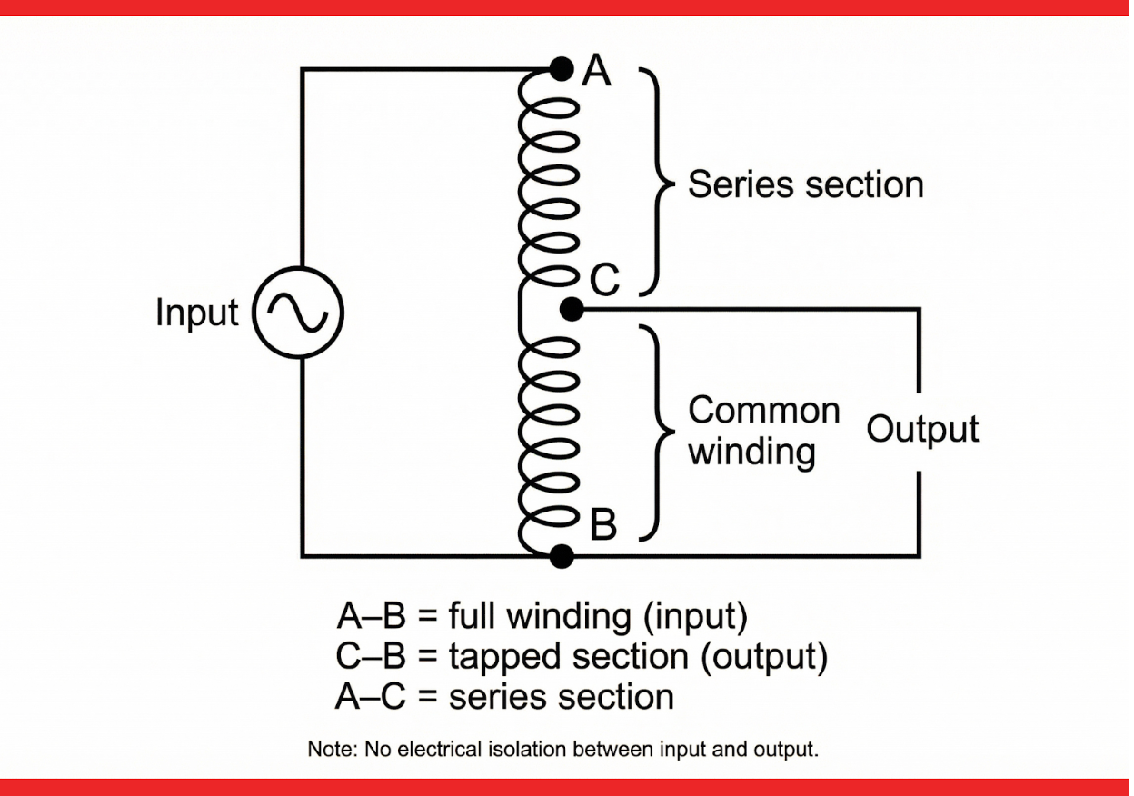
In this diagram:
- The full winding is connected to the input
- The output is taken from a tap on the same winding
- There is no physical separation between primary and secondary
This contrasts with isolation transformers, where primary and secondary windings are completely separate.
Key Differences Between Autotransformers and Isolation Transformers
The defining feature of an autotransformer is the lack of galvanic isolation. This has important implications for safety, grounding, and fault behavior.
Key distinctions include:
- Autotransformers share a winding; isolation transformers do not
- Autotransformers are smaller and lighter for the same kVA
- Autotransformers are typically more efficient
- Isolation transformers provide electrical separation and improved safety
Because of these differences, the two transformer types are not interchangeable.
Advantages of Autotransformers
Autotransformers offer several practical benefits when isolation is not required.
They are:
- Smaller and lighter, making installation easier
- More efficient, with lower losses
- Lower cost, due to reduced copper and core material
- Lower impedance, resulting in better voltage regulation
These advantages make autotransformers attractive for applications where voltage adjustment is needed without added complexity.
Limitations and Safety Considerations
The primary limitation of an autotransformer is that the input and output are electrically connected. This means:
- Faults on one side can propagate to the other
- Grounding conditions are shared
- There is reduced protection against electrical shock
- Higher fault currents may be present
Because of these factors, autotransformers are not suitable where isolation is required by electrical code, safety standards, or application requirements.
Typical Uses of Autotransformers
Autotransformers are commonly used in applications where voltage needs to be adjusted but isolation is unnecessary.
Common uses include:
- Buck-boost voltage correction (small voltage changes)
- Motor starting (reduced voltage starting)
- Voltage matching between similar systems (e.g., 600 V to 480 V)
- Industrial equipment with compatible grounding systems
- Laboratory or test setups where isolation is not required
They are especially popular when space and efficiency are priorities.
When Not to Use an Autotransformer
Autotransformers should generally be avoided when:
- Electrical isolation is required
- A separately derived system is needed
- Sensitive or critical loads are involved
- Grounding flexibility is important
- Safety considerations outweigh cost and size benefits
In these cases, an isolation transformer is the safer and more appropriate choice.
Autotransformers in Modern Power Systems
In modern electrical systems, autotransformers continue to play an important role, particularly in industrial and utility applications. When applied correctly, they provide a highly efficient and economical solution for voltage transformation.
However, proper understanding of their limitations is essential. Misapplication—especially where isolation is required—can lead to safety risks and system performance issues.
Conclusion
An autotransformer is a simple and efficient way to change voltage levels using a single winding. Its compact size, high efficiency, and lower cost make it an attractive option for many applications. However, the lack of electrical isolation means it must be applied carefully.
Understanding how autotransformers work—and when they should or should not be used—allows engineers and system designers to take advantage of their benefits while avoiding potential risks.
Transformer Electrical Symbols: A Guide to Transformer Symbols in Electrical Diagrams
Electrical diagrams are the language of power systems, and transformer symbols are a critical part of that language. Whether reviewing single-line diagrams, schematics, or equipment layouts, understanding transformer symbols allows engineers, electricians, and facility managers to quickly interpret system configuration, voltage transformation, grounding, and protection intent.
Transformer symbols may look simple, but subtle variations communicate important information about winding connections, grounding, phase configuration, and function. This article provides a practical guide to common transformer electrical symbols, explaining what they represent and how to interpret them correctly in electrical diagrams.
Why Transformer Symbols Matter
Transformer symbols are not just graphical placeholders. They convey essential design intent, including:
- Whether the transformer is single-phase or three-phase
- How the primary and secondary windings are connected
- Whether a neutral is present and how it is grounded
- Whether the transformer provides isolation or voltage adjustment
Misinterpreting a transformer symbol can lead to incorrect assumptions about grounding, fault behavior, or system compatibility. For this reason, familiarity with common transformer symbols is essential for anyone working with electrical drawings.
Basic Transformer Symbol
The most fundamental transformer symbol represents two magnetically coupled windings separated by a core.
In simplified form, a transformer is shown as:
- Two parallel coils or windings
- A line or set of lines between them representing the magnetic core
This basic symbol indicates voltage transformation but does not specify phase, grounding, or winding configuration. Additional markings are required to convey that information.
Single-Phase Transformer Symbols
- Single-phase transformers are commonly used in control circuits, lighting systems, and smaller power applications.
A typical single-phase transformer symbol shows:
- One primary winding
- One secondary winding
- Optional indication of a center tap on the secondary
When a center tap is present, it is usually drawn as a connection at the midpoint of the secondary winding, indicating the availability of two equal secondary voltages.
Single-phase symbols are often used in detailed schematics rather than high-level one-line diagrams.
Three-Phase Transformer Symbols
- Three-phase transformer symbols are most commonly shown in single-line diagrams, where each phase is represented by a single line rather than three separate conductors.
A three-phase transformer symbol typically includes:
- A simplified transformer icon
- Labels indicating primary and secondary voltages
- Connection symbols indicating delta or wye configurations
Even though only one line is drawn, the symbol represents all three phases of the transformer.
Delta and Wye Connection Symbols
Transformer winding connections are often shown using delta (Δ) and wye (Y) symbols near the transformer.
- Delta (Δ) indicates that the winding is connected in a closed loop with no neutral
- Wye (Y) indicates that the winding has a neutral point
If the neutral is grounded, a grounding symbol is shown connected to the neutral point. These symbols are critical for understanding system grounding, fault current behavior, and neutral availability.
For example:
Δ–Y indicates a delta-connected primary and wye-connected secondary
Yg–Δ indicates a grounded wye primary and delta secondary
Grounded Neutral Symbols
Grounding is one of the most important pieces of information conveyed in transformer symbols.
A grounded neutral is typically shown by:
- A grounding symbol connected to the neutral point
- A “g” or similar notation next to the wye symbol
This indicates that the transformer creates a grounded reference point, which affects ground-fault protection, surge behavior, and system stability.
Ungrounded or impedance-grounded systems may be shown without a direct ground symbol or with additional components such as grounding resistors or reactors.
Autotransformer Symbols
Autotransformers are represented differently from isolation transformers because they use a single winding with taps rather than separate primary and secondary windings.
An autotransformer symbol typically shows:
- A single winding
- One or more taps along the winding
- Input and output connections on the same winding
The lack of separation between windings visually reinforces that there is no electrical isolation between input and output.
Current Transformer (CT) Symbols
Current transformers are used for metering and protection rather than power transformation.
CT symbols typically include:
- A conductor passing through a core or window
- A secondary winding shown around the core
- Polarity markings such as dots or “H1 / X1” labels
These symbols indicate that the CT output is proportional to current, not voltage, and that correct polarity is important for protection and metering accuracy.
Potential / Voltage Transformer (PT or VT) Symbols
Potential transformers, also called voltage transformers, are used to step down voltage for measurement and protection.
PT symbols resemble small power transformers but are often labeled explicitly as PT or VT. They may include:
- Fuse symbols on the primary side
- Grounding symbols on one side of the secondary
These details indicate that the transformer is intended for measurement rather than power delivery.
Polarity Dots and Terminal Markings
Some transformer symbols include polarity dots on windings. These dots indicate the relative instantaneous polarity between primary and secondary windings.
Polarity markings are essential for:
- Parallel transformer operation
- Correct phase relationships
- Proper CT and PT connections
Ignoring polarity markings can result in circulating currents, incorrect measurements, or protection misoperation.
Transformer Symbols in One-Line vs. Schematic Diagrams
Transformer symbols vary depending on the type of diagram being used.
- One-line diagrams use simplified symbols focused on system topology
- Schematic diagrams use detailed symbols showing individual windings and connections
Understanding the context of the drawing helps interpret how much detail the transformer symbol is intended to convey.
Common Misinterpretations of Transformer Symbols
A frequent mistake is assuming that all transformers provide isolation. Autotransformer symbols, if not recognized, can be mistaken for isolation transformers.
Another common issue is overlooking grounding symbols, leading to incorrect assumptions about neutral availability or ground-fault behavior. Careful attention to connection and grounding indicators is essential.
Conclusion
Transformer electrical symbols provide a compact but powerful way to communicate critical information about power systems. By understanding how to read symbols for transformer type, winding configuration, grounding, and function, engineers and technicians can interpret electrical diagrams with confidence.
Whether reviewing a high-level one-line diagram or a detailed schematic, recognizing transformer symbols is an essential skill in modern electrical power systems.
Transformer Polarity Explained: Polarity of a Transformer and Why It Matters
Transformer polarity is a fundamental concept that plays a critical role in how transformers interact with electrical systems. While polarity is often treated as a commissioning or installation detail, it directly affects voltage relationships, parallel operation, metering accuracy, and protection performance.
Incorrect polarity connections can result in additive voltages, circulating currents, misoperation of protection devices, or immediate equipment damage. Understanding transformer polarity what it means, how it is identified, and why it matters is essential for engineers, electricians, and technicians working with power and distribution transformers.
This article explains transformer polarity in practical terms and highlights why it must be verified before transformers are energized or interconnected.
What Is Transformer Polarity?
Transformer polarity describes the relative instantaneous direction of voltage between the primary and secondary windings. In other words, it indicates whether the primary and secondary voltages rise and fall in the same direction at a given moment in time.
Polarity is determined by how the windings are wound and connected around the core. It does not affect the transformer’s voltage ratio, efficiency, or kVA rating, but it has a major impact on how transformers behave when connected to other equipment or to each other.
Why Transformer Polarity Matters
Transformer polarity becomes critical whenever voltages are combined, compared, or shared.
Incorrect polarity can cause:
- Additive voltages instead of subtractive voltages
- Circulating currents between parallel transformers
- Incorrect phase relationships in three-phase systems
- Metering and protection errors
- Immediate overvoltage or short-circuit conditions
For these reasons, polarity must always be confirmed before paralleling transformers, connecting secondaries together, or energizing control circuits.

Polarity in Single-Phase Transformers
In single-phase transformers, polarity is commonly classified as either additive or subtractive.
Subtractive Polarity
Subtractive polarity means that when primary and secondary windings are connected in series, the secondary voltage subtracts from the primary voltage. This is the most common polarity for distribution and power transformers.
Subtractive polarity is typically used in:
- Medium- and high-voltage transformers
- Distribution transformers
- Industrial power applications
Most modern transformers are built with subtractive polarity unless otherwise specified.
Additive Polarity
Additive polarity means that primary and secondary voltages add together when connected in series. This configuration is more common in smaller transformers, such as control or instrument transformers.
Additive polarity may be found in:
- Small single-phase control transformers
- Low-voltage applications
- Special-purpose equipment
Because additive polarity can produce higher combined voltages, it requires careful attention during installation.
Polarity Dots and Terminal Markings
Transformer polarity is usually indicated using polarity dots or standardized terminal markings.
A polarity dot placed on each winding indicates corresponding instantaneous polarity. When the dotted ends of the primary and secondary are positive at the same time, the transformer is said to be correctly marked.
Terminal markings such as H1, H2 (primary) and X1, X2 (secondary) also convey polarity information. Connecting H1 and X1 together typically results in a subtractive polarity configuration for most power transformers.
Understanding these markings is essential when interpreting drawings and making field connections.
Polarity in Three-Phase Transformers
In three-phase transformers, polarity extends beyond simple additive or subtractive behavior. It is closely tied to phase rotation, vector group, and winding configuration.
Three-phase polarity affects:
- Phase displacement between primary and secondary
- Compatibility for parallel operation
- System grounding behavior
For three-phase transformers, polarity is often expressed as part of a vector designation, which defines how secondary voltages are phase-shifted relative to the primary.
Impact of Polarity on Parallel Operation
Transformer polarity is especially critical when transformers operate in parallel. Even if voltage ratings, impedance, and kVA match, incorrect polarity will prevent proper load sharing.
If polarity is mismatched:
- Transformers may oppose each other
- High circulating currents can flow
- Overheating and damage may occur rapidly
Correct polarity alignment is therefore a prerequisite for parallel transformer operation, along with impedance and voltage ratio matching.
Polarity and Metering / Protection
Instrument transformers such as current transformers (CTs) and potential transformers (PTs) rely heavily on correct polarity.
Incorrect polarity can cause:
- Reversed power or energy readings
- Differential protection misoperation
- Incorrect fault detection
In protection schemes, polarity errors can defeat the intended function of relays, leading to false trips or failure to trip during faults.
How Transformer Polarity Is Verified
Transformer polarity is typically verified during factory testing and again during field installation.
Common methods include:
- Voltage comparison tests using a known source
- Polarity test connections on single-phase units
- Phasing checks on three-phase transformers
Polarity testing is a standard commissioning step and should never be skipped, even when transformers appear identical.
Common Polarity-Related Mistakes
Many polarity issues arise from assumptions rather than technical errors. Common mistakes include:
- Assuming all transformers have the same polarity
- Ignoring terminal markings
- Misinterpreting schematic symbols
- Failing to test polarity before paralleling units
Because polarity errors can cause immediate problems, verification is far less costly than troubleshooting after energization.
Conclusion
Transformer polarity defines the relative voltage relationship between windings and plays a critical role in system performance, safety, and reliability. While it may seem like a small detail, incorrect polarity can lead to serious operational issues, from circulating currents to protection failures.
By understanding transformer polarity, recognizing polarity markings, and verifying polarity during installation, engineers and technicians can ensure transformers operate as intended. Polarity is not just a theoretical concept—it is a practical requirement for safe and reliable power systems.
3-Phase Transformer Wiring Diagrams Explained
Three-phase transformers are the backbone of modern power distribution, supplying energy to industrial facilities, commercial buildings, and utility networks. To understand how these transformers are applied in real systems, engineers and electricians rely heavily on 3-phase transformer wiring diagrams.
At first glance, these diagrams can appear complex. However, once the basic connection types and symbols are understood, wiring diagrams become a powerful tool for interpreting voltage relationships, grounding methods, and system behavior. This article explains the most common 3-phase transformer wiring diagrams, how to read them, and what they reveal about system operation.
What Is a 3-Phase Transformer Wiring Diagram?
A 3-phase transformer wiring diagram is a graphical representation of how transformer windings are connected on the primary and secondary sides. Depending on the drawing type, it may show:
- Winding connections (delta, wye, zig-zag)
- Phase relationships
- Neutral connections and grounding
- Voltage transformation
- Terminal designations
Most system-level drawings use single-line diagrams, where one line represents all three phases. More detailed schematic diagrams may show individual windings and terminals.
Understanding the diagram format is the first step in interpreting the wiring.
Common 3-Phase Transformer Connection Types
The majority of 3-phase transformer wiring diagrams fall into a small number of standard connection types. Each has distinct electrical characteristics and applications.
Delta–Delta (Δ–Δ) Connection
In a delta–delta transformer, both the primary and secondary windings are connected in a closed delta loop.
This connection:
- Does not provide a neutral
- Is tolerant of unbalanced loads
- Can continue operating with one transformer winding out of service (open-delta operation)
- Blocks zero-sequence currents
Delta–delta wiring diagrams are common in older industrial systems and some utility applications where grounding is handled elsewhere.
Delta–Wye (Δ–Y) Connection
The delta–wye connection is one of the most widely used configurations in power distribution.
In this arrangement:
- The primary is delta-connected
- The secondary is wye-connected
- A neutral is available on the secondary side
Delta–wye wiring diagrams often indicate whether the wye neutral is grounded. This configuration provides isolation between primary and secondary grounding systems and helps manage harmonics and fault currents.
Wye–Delta (Y–Δ) Connection
In a wye–delta transformer, the primary winding is wye-connected and the secondary winding is delta-connected.
This configuration:
- Is commonly used to supply motor loads
- Eliminates the need for a secondary neutral
- Helps isolate downstream faults from the supply
- Requires careful grounding on the primary side
Wiring diagrams for wye–delta transformers typically emphasize grounding of the primary neutral.
Wye–Wye (Y–Y) Connection
Wye–wye transformers have both primary and secondary windings connected in wye.
While this configuration provides neutrals on both sides, it requires careful grounding and design consideration to avoid issues such as neutral instability or voltage imbalance.
Wye–wye wiring diagrams often include grounding resistors, grounding transformers, or other stabilization methods to ensure proper operation.

Zig-Zag and Grounding Transformer Diagrams
Zig-zag transformers are used primarily for grounding and neutral creation rather than voltage transformation.
In wiring diagrams, zig-zag connections are shown with interleaved winding arrangements. These diagrams indicate:
- Creation of a neutral point
- Path for zero-sequence currents
- Ground-fault current control
Zig-zag wiring diagrams are common in grounding applications and harmonic mitigation systems.
Reading Voltage Information on Wiring Diagrams
Transformer wiring diagrams often include voltage labels that show:
- Primary line-to-line voltage
- Secondary line-to-line voltage
- Secondary line-to-neutral voltage (if applicable)
Understanding whether voltages are expressed as line-to-line or line-to-neutral is essential. Misinterpreting these values can lead to incorrect equipment selection or unsafe installations.
Grounding Shown in 3-Phase Wiring Diagrams
Grounding is a critical part of transformer wiring diagrams. It may be shown as:
- A solidly grounded neutral
- A resistor-grounded neutral
- An ungrounded system
- A grounding transformer connection
The grounding method affects fault current magnitude, surge protection, and protection coordination. Wiring diagrams clearly indicate grounding intent, and these details must be followed precisely during installation.
Phase Rotation and Polarity in Diagrams
Three-phase wiring diagrams implicitly define phase rotation and polarity. When transformers are paralleled or connected to rotating machinery, correct phase sequence is essential.
Polarity dots, terminal markings, and vector group notations may appear in more detailed diagrams. These indicators help ensure compatibility between transformers and the systems they serve.
One-Line vs. Detailed Schematic Diagrams
Most system drawings use one-line diagrams for clarity and simplicity. These show transformer connections symbolically rather than depicting every conductor.
Detailed schematics may be used for:
- Control circuits
- Protection schemes
- Factory testing
- Troubleshooting
Knowing which type of diagram you are viewing helps set expectations about the level of detail provided.
Common Wiring Diagram Mistakes
Misinterpretation of transformer wiring diagrams can lead to serious issues. Common mistakes include:
- Assuming a neutral exists when it does not
- Overlooking grounding details
- Misreading delta and wye symbols
- Confusing line-to-line and line-to-neutral voltages
- Ignoring polarity or phase rotation
Careful review of diagrams before installation prevents costly errors.
Conclusion
3-phase transformer wiring diagrams provide essential insight into how transformers interact with electrical systems. By understanding common connection types, grounding methods, and voltage relationships, engineers and electricians can interpret these diagrams with confidence.
Whether reviewing a high-level one-line diagram or a detailed schematic, the ability to read and understand 3-phase transformer wiring diagrams is a fundamental skill in power system design and installation.