Autotransformer vs. Isolation Transformer: Pros, Cons, and When to Use Each
Transformers are widely used to adapt voltage levels, improve system compatibility, and enhance safety in electrical power systems. Among the most common transformer types are autotransformers and isolation transformers. While both perform voltage transformation, they differ significantly in construction, electrical behavior, safety characteristics, and suitable applications.
Selecting the wrong transformer type can lead to safety risks, grounding complications, protection issues, or unnecessary costs. This article explains the key differences between autotransformers and isolation transformers, outlines their advantages and limitations, and provides guidance on when each type is most appropriate.
What Is an Autotransformer?
An autotransformer uses a single continuous winding that serves as both the primary and secondary. Part of the winding is common to both the input and output, with taps providing the desired voltage transformation.
Because energy is transferred both magnetically and electrically through the shared winding, autotransformers are smaller and more efficient than isolation transformers for the same kVA rating. However, this shared winding means there is no electrical isolation between the input and output circuits.
Autotransformers are typically used where the voltage change is modest, and isolation is not required.
What Is an Isolation Transformer?
An isolation transformer uses separate primary and secondary windings, with no direct electrical connection between them. Power is transferred purely through magnetic coupling via the core.
This separation provides galvanic isolation, meaning faults, transients, and ground potential differences on one side are not directly transferred to the other. Isolation transformers are widely used where safety, noise reduction, or grounding control is important.
Although they are generally larger and heavier than autotransformers, isolation transformers offer significantly greater protection and flexibility.
Key Differences in Construction and Operation
The most fundamental difference between autotransformers and isolation transformers lies in how their windings are arranged.
An autotransformer shares part of its winding between the input and output, which reduces material usage and losses. An isolation transformer keeps windings completely separate, increasing size and cost but improving safety and system control. Because of this difference, autotransformers transfer some power conductively, while isolation transformers transfer power only magnetically.
These construction differences drive the practical advantages and limitations of each design.
Autotransformer vs. Isolation Transformer: Key Differences

Advantages of Autotransformers

Autotransformers offer practical benefits when isolation is not required. Their reduced size and weight make them easier to install in space-constrained environments, and the lower material content results in lower cost. They also tend to be more efficient and exhibit lower impedance, which improves voltage regulation under load.
These characteristics make autotransformers attractive for applications where efficiency, size, and cost are key priorities.
Limitations of Autotransformers
The primary limitation of an autotransformer is the lack of electrical isolation. Faults, surges, or ground potential differences on one side can propagate directly to the other, reducing safety and limiting fault containment.
Autotransformers also offer limited grounding flexibility and typically result in higher available fault current, which can complicate protection coordination. As a result, they are generally unsuitable where isolation is required by code, safety standards, or application needs.
Advantages of Isolation Transformers
Isolation transformers provide full electrical separation between source and load. This improves personnel safety, reduces electrical noise, and allows designers to establish a new grounding reference on the secondary side.
They are particularly valuable in applications where fault containment, grounding control, or noise reduction is critical, such as sensitive electronic systems, industrial processes, and healthcare environments.
Limitations of Isolation Transformers
The main trade-offs associated with isolation transformers are size, weight, and cost. Because they require separate windings and additional insulation, isolation transformers are larger and heavier than autotransformers of the same kVA rating.
They also tend to have higher impedance, which can result in greater voltage drop under load. However, this impedance can be beneficial for limiting fault current and improving protection coordination.
Grounding and Safety Considerations
Grounding behavior is one of the most significant differences between autotransformers and isolation transformers. With an autotransformer, grounding on the primary side directly affects the secondary, limiting grounding options and increasing risk.
Isolation transformers allow the secondary system to be grounded independently, making them ideal for separately derived systems, controlled grounding schemes, and applications requiring enhanced safety and fault isolation.
Typical Applications
Autotransformers are commonly used where voltage adjustment is required without isolation, such as buck-boost applications, motor starting, and voltage matching between similar systems.
Isolation transformers are preferred where safety, noise reduction, or grounding flexibility is essential, including sensitive electronic loads, industrial systems, and installations governed by strict electrical code requirements.
Choosing the Right Transformer
The choice between an autotransformer and an isolation transformer should be driven by application requirements rather than cost alone. Where isolation, grounding control, or safety is critical, an isolation transformer is the correct choice. Where efficiency, size, and cost are priorities and isolation is not required, an autotransformer may be appropriate.
Conclusion
Autotransformers and isolation transformers serve distinct roles in modern power systems. Autotransformers provide compact, efficient, and cost-effective voltage transformation where isolation is not required. Isolation transformers deliver enhanced safety, grounding flexibility, and fault containment where electrical separation is essential.
Understanding the differences between these transformer types allows engineers to make informed decisions that improve safety, reliability, and system performance.
Equivalent Circuit of a Transformer Explained: How It Models Real Transformer Losses
Transformers are often described as simple devices: two windings, a magnetic core, and no moving parts. In reality, transformer behavior is influenced by losses, leakage flux, and non-ideal characteristics that affect efficiency, voltage regulation, and thermal performance. To understand and predict this real-world behavior, engineers rely on the equivalent circuit of a transformer.
The equivalent circuit is a simplified electrical model that represents how a transformer behaves under load. It allows engineers to analyze losses, calculate voltage drop, estimate efficiency, and evaluate performance under different operating conditions. This article explains the transformer equivalent circuit in practical terms and shows how it represents real transformer losses without resorting to excessive mathematics.

Why an Equivalent Circuit Is Needed
An ideal transformer would transfer power with no losses, no voltage drop, and perfect magnetic coupling. Real transformers, however, experience:
- Core losses due to magnetization
- Conductor losses due to winding resistance
- Voltage drop caused by leakage reactance
- Heating that limits continuous loading
The equivalent circuit provides a way to model these effects using familiar electrical components such as resistors and inductors. By representing physical phenomena as circuit elements, engineers can analyze transformer performance using standard circuit techniques.
Overview of the Transformer Equivalent Circuit
The transformer equivalent circuit is composed of two main parts:
- The magnetizing (excitation) branch, which represents core behavior
- The series impedance branch, which represents winding resistance and leakage reactance
- These elements together describe how the transformer behaves under both no-load and load conditions.
Although the equivalent circuit can be drawn in several forms, all versions represent the same physical effects.
The Magnetizing Branch: Modeling Core Behavior
The magnetizing branch is connected in parallel with the ideal transformer and represents what happens in the core when voltage is applied.
Core Loss Resistance
One component of the magnetizing branch is a resistance that represents core (no-load) losses. These losses occur whenever the transformer is energized, regardless of load, and are primarily due to:
- Hysteresis losses in the core material
- Eddy current losses within the laminations
- This resistance models the real power consumed by the core and explains why transformers draw power even at no load.
Magnetizing Reactance
The other component of the magnetizing branch is the magnetizing reactance, which represents the current required to establish magnetic flux in the core. This current is largely reactive and does not transfer power to the load.
Magnetizing current:
- Exists whenever the transformer is energized
- Is typically a small percentage of the rated current
- Increases if the core approaches saturation
Together, the core loss resistance and magnetizing reactance explain the no-load current, the no-load losses, and the effects of core saturation.
The Series Impedance: Modeling Winding Effects
The series elements of the equivalent circuit represent losses and voltage drop associated with the windings.
Winding Resistance
Each transformer winding has finite electrical resistance. This resistance causes conductor losses, often referred to as load losses, which increase with the square of load current.
These losses:
- Are negligible at no load
- Increase rapidly as the load increases
- Contribute directly to the winding temperature rise
In the equivalent circuit, winding resistance accounts for real power loss and heating under load.
Leakage Reactance
Leakage reactance represents magnetic flux that does not link both windings. This leakage flux produces inductive reactance that limits current and causes voltage drop under load.
Leakage reactance:
- Is a function of winding geometry and spacing
- Dominates transformer impedance
- Helps limit short-circuit current
In practical terms, leakage reactance explains why transformer secondary voltage decreases as load increases.
Referring to the Equivalent Circuit to One Side
For analysis convenience, all elements of the equivalent circuit are often referred to either the primary or secondary side. This is done by scaling resistances and reactances by the square of the turns ratio.
Referring to the circuit to one side:
- Simplifies calculations
- Allows transformer behavior to be analyzed as a single circuit
- Does not change the physical meaning of losses or impedance
This approach is widely used in system studies and performance calculations.
How the Equivalent Circuit Models Transformer Losses
The equivalent circuit separates transformer losses into two distinct categories:
- No-Load (Core) Losses
- Represented by the core loss resistance
- Present whenever the transformer is energized
- Independent of load
- Load (Conductor) Losses
- Represented by winding resistance
- Increase with load current
- Responsible for most heating under load
This separation helps engineers understand why lightly loaded transformers may still consume power and why heavily loaded transformers experience rapid temperature rise.
Voltage Regulation and the Equivalent Circuit
Voltage regulation describes the change in secondary voltage from no load to full load. In the equivalent circuit, voltage regulation is primarily caused by:
- Winding resistance
- Leakage reactance
As load current flows through the series impedance, a voltage drop occurs. The magnitude of this drop depends on the impedance value and the power factor of the load. Lagging power factor loads generally experience greater voltage drop due to reactance.
Efficiency Analysis Using the Equivalent Circuit
Transformer efficiency is calculated by comparing output power to total input power. The equivalent circuit makes this possible by clearly identifying loss components.
Efficiency depends on:
Core losses (constant with load)
Load losses (varying with current)
The equivalent circuit allows engineers to determine the load point at which efficiency is maximized and to evaluate how efficiency changes with operating conditions.
Limitations of the Equivalent Circuit
While the equivalent circuit is extremely useful, it has limitations. It assumes linear behavior and does not fully capture:
- Core saturation effects at high flux
- Harmonic distortion from non-sinusoidal loads
- Temperature-dependent changes in resistance
- Mechanical effects during short-circuit events
Despite these limitations, the equivalent circuit remains a powerful and widely used modeling tool for transformer analysis.
Conclusion
The equivalent circuit of a transformer provides a practical framework for understanding how real transformers behave. By representing core losses, magnetizing current, winding resistance, and leakage reactance with simple circuit elements, it allows engineers to analyze losses, voltage regulation, and efficiency with clarity.
Although simplified, the equivalent circuit bridges the gap between physical transformer construction and system-level performance. For designers, specifiers, and operators alike, it remains an essential tool for understanding and applying transformers in real power systems.
Transformer Impedance Matching: Concepts, Tolerances, and Practical Application
Transformer impedance is often discussed in the context of fault current limitation, but its role in impedance matching is just as critical—particularly when transformers operate in parallel or supply common loads. Impedance matching affects how load current is shared, how voltages behave under load, and how reliably transformers operate over time.
Poor impedance matching can lead to circulating currents, uneven loading, excessive heating, and reduced transformer life, even when transformers appear compatible on paper. Understanding how impedance works, how matching is achieved, and what level of mismatch is acceptable allows engineers to design systems that operate predictably and reliably. This article explains transformer impedance matching in practical terms, including commonly accepted tolerances used in real-world power systems.
What Is Impedance Matching in Transformers?
In power systems, impedance matching does not mean matching transformer impedance to the load, as is done in signal or communications systems. Instead, impedance matching refers to ensuring that transformers connected to the same electrical system—most often in parallel—have compatible impedance characteristics.
The objective of impedance matching is to:
- Ensure balanced load sharing
- Prevent circulating currents between transformers
- Maintain stable voltage regulation
- Avoid thermal overstress of windings
Impedance matching is therefore about compatibility and proportionality, not exact equality.
Why Impedance Matching Matters
Parallel Transformer Operation
When transformers operate in parallel, their impedances determine how load current divides between them. Transformers do not inherently “know” their kVA ratings; they share load according to impedance.
If two transformers have different impedances, the transformer with lower impedance will carry a greater share of the load, while the higher-impedance unit will carry less. Under heavy loading, this imbalance can cause one transformer to overload and overheat even though the combined load is within the total installed capacity.
Circulating Currents
Impedance mismatch—especially when combined with small voltage ratio differences—can cause circulating currents between transformers. These currents do not supply the load but still generate losses and heat within the windings, reducing efficiency and accelerating insulation aging.
Voltage Regulation and Stability
Transformers with different impedances experience different voltage drops as the load increases. When operating together, this can lead to unequal secondary voltages and unstable load sharing, particularly during load changes.
Transformer Impedance Fundamentals
Transformer impedance is expressed as a percentage (%) or per-unit (pu) value and represents the voltage required to drive rated current through the transformer under short-circuit conditions.
Impedance is made up of:
- Resistance, which contributes to conductor losses and heating
- Leakage reactance, which dominates impedance and limits fault current
- Leakage reactance is determined primarily by winding geometry and spacing. As a result, impedance is fundamentally a design characteristic and cannot be adjusted once the transformer is manufactured.
How Impedance Affects Load Sharing
When transformers operate in parallel, load sharing is inversely proportional to impedance. In simple terms, lower impedance means higher load share.
The relationship can be expressed as: I1/I2 = Z2/Z1
This explains why even modest differences in impedance can produce significant differences in current distribution, particularly under high or continuous loading.
Acceptable Impedance Tolerance for Parallel Transformers
In practice, transformer impedances are never exactly identical. Manufacturing tolerances, design choices, and rating differences all introduce variation. The key question is how much variation can be tolerated without causing unacceptable load imbalance.
For transformers of equal kVA rating, industry practice generally considers the following impedance tolerance acceptable:
- Within ±7.5% of the average impedance value
- Preferably within ±5% for critical or continuously loaded applications
As an example, two 1000 kVA transformers with impedances of 5.0% and 5.3% will usually share load satisfactorily. However, pairing a 5.0% unit with a 6.0% unit may result in noticeable imbalance, particularly as loading approaches rated capacity.
For transformers of unequal kVA ratings, proper load sharing requires impedance values to be inversely proportional to kVA rating. Even when this proportionality is achieved, impedance tolerance should still remain within similar per-unit limits to ensure stable operation.
It is also important to consider the X/R ratio. While percent impedance governs steady-state load sharing, differences in X/R ratio influence dynamic behavior during load changes and fault events. Significant X/R mismatch can lead to transient circulating currents even when percent impedance appears acceptable.
When Tighter Impedance Matching Is Advisable
More restrictive impedance tolerances should be considered when:
- Transformers operate near full load on a continuous basis
- Harmonic content is significant
- Loads are sensitive or mission-critical
- Transformers are from different manufacturers or design families
- Long service life and thermal margin are priorities
In these cases, specifying impedance tolerance closer to ±5%—or confirming acceptability with the manufacturer—is strongly recommended.
Impedance Matching vs. Fault Current Limitation
Transformer impedance also plays a key role in limiting short-circuit current. Designers must balance the desire for lower impedance (better voltage regulation and load sharing) against the benefits of higher impedance (reduced fault current and easier protection coordination).
This trade-off is resolved during transformer design and specification. Once installed, impedance cannot be changed without adding external components such as reactors.
Common Misconceptions About Impedance Matching
A common misconception is that transformers with the same kVA rating are automatically suitable for parallel operation. In reality, impedance variation between designs—or even between production runs—can prevent proper load sharing.
Another misconception is that impedance matching only matters for large transformers. In practice, mismatches can be problematic even in smaller systems, especially where loads are continuous or thermal margin is limited.
Conclusion
Transformer impedance matching is essential for stable parallel operation, balanced load sharing, and long-term reliability. While exact impedance equality is not required, excessive mismatch leads to circulating currents, overheating, and reduced transformer life.
Understanding impedance concepts, applying accepted tolerance guidelines, and verifying compatibility before paralleling transformers are simple but critical steps in sound power system design. When impedance matching is addressed early, transformers integrate smoothly into the system and perform as intended throughout their service life.
Transformer Windings: Design, Materials and Performance
Updated: August 17th, 2026
A transformer may meet the required kVA, voltage ratio and temperature-rise rating on paper, yet behave differently from another unit with the same nameplate values. The difference often begins in the windings.
Conductor material, winding geometry, insulation, cooling passages and mechanical support influence losses, impedance, voltage regulation, short-circuit strength, hot-spot temperature and insulation life. Improving one characteristic can make another more difficult. Tighter magnetic coupling can reduce voltage drop, for example, but it also lowers impedance and increases available fault current.
Understanding transformer windings therefore requires more than identifying the primary and secondary coils. It requires examining how electrical, thermal and mechanical decisions interact within the complete transformer.
What Transformer Windings Actually Do
Alternating current in the primary winding produces alternating magnetic flux in the core. That changing flux induces voltage in the secondary winding. The relationship between the number of turns establishes the approximate voltage ratio, while conductor size and cooling determine how much current each winding can carry within its temperature limits.
The same principle applies whether the transformer steps voltage up, steps it down or uses an approximately 1:1 ratio. In a general-purpose isolation transformer, the primary and secondary remain electrically separated even when their nominal voltages are equal.
The turns ratio is only the starting point. Windings must also withstand continuous current, dielectric stress, repeated thermal expansion and contraction, vibration and fault forces. A winding that produces the correct voltage but cannot control heat or mechanical movement is not a successful design.
Copper and Aluminum Are Design Choices, Not Quality Grades
Transformer windings are commonly made from copper or aluminum. Copper has higher electrical conductivity, so it can carry a given current with a smaller cross-sectional area. Aluminum requires more conductor area for comparable performance, but its lower density can reduce winding weight, and its material cost is typically lower.

Neither material is universally better. The larger aluminum conductor affects winding dimensions, clearances, cooling spaces, supports and terminations. Copper may suit restricted spaces or compact designs. Aluminum may suit projects where weight and cost carry more importance. Either can provide reliable service when current density, losses, temperature rise, connections and mechanical support are engineered around it.
Conductor form matters as well. Round wire, rectangular wire, strip, foil and parallel conductors arrange the available conductor area differently. Foil is commonly used on low-voltage, high-current windings because its broad surface can suit the current level, geometry and heat-transfer requirements. Selection depends on voltage, current, insulation build, cooling and short-circuit forces.
Winding Geometry Sets the Electrical Trade-Offs
Primary and secondary windings are commonly arranged concentrically around a core leg, using layers, discs, foil sections or other configurations suited to the rating. Their physical relationship controls magnetic coupling and leakage flux.
Closer coupling generally reduces leakage reactance and percent impedance. This supports better voltage regulation because less voltage is lost internally as load current rises. The trade-off is higher available fault current. Increasing separation generally raises impedance, which limits fault current but can increase voltage drop.
Spacing cannot be selected from the impedance target alone. The design must also provide dielectric clearances, cooling ducts and mechanical support. A change made to improve airflow or insulation distance can also change impedance. Percent impedance is therefore a winding-design result, not simply a catalogue value added later.
Three-phase connection also changes system behaviour. Delta, wye and zig-zag arrangements affect voltage relationships, neutral availability, grounding, phase shift, harmonic paths and zero-sequence behaviour. The correct connection depends on the source, grounding method, load and protection strategy. For a closer look at how each connection affects voltage, grounding, phase shift and system behaviour, read our guide on wye vs. delta, discussing connection choices and what they mean in practice.
Insulation Is Part of the Winding Structure

Winding insulation separates adjacent turns, layers, winding sections, primary and secondary circuits, the core and grounded structural parts. These locations do not experience the same electrical stress. Turn-to-turn voltage may be relatively small during normal operation, while winding-to-ground and winding-to-winding insulation may need to withstand the full system voltage and transient overvoltages.
The insulation system must therefore be coordinated with voltage class, geometry, clearances, transient requirements and manufacturing process. Dry-type construction may use vacuum pressure impregnated (VPI) or vacuum pressure encapsulated (VPE) windings, cast coil windings or other resin-based systems.
Insulation class describes the thermal capability of the complete system. It does not remove the need to control temperature. Ambient conditions, winding rise, hot-spot allowance, loading and cooling must remain coordinated.
Medium-voltage winding design must also control partial discharge. Voids, sharp electrical stress concentrations or inadequate impregnation can allow localized discharge that gradually erodes insulation. Material selection alone does not solve this problem; geometry, processing quality and electric-field control also matter.
Heat Is Produced Unevenly Inside the Winding
Current produces conductor losses commonly expressed as I²R losses. Because these losses increase with the square of current, a modest overload can produce a much larger increase in winding heat. Leakage flux also creates stray and eddy-current losses, and those losses are not distributed uniformly.
The temperature pattern matters more than the average alone. A transformer can have an acceptable average winding temperature while a restricted cooling path or high-loss region creates a local hot spot. That hot spot ages insulation faster and can limit transformer life.
Conductor surface area, winding dimensions, cooling ducts, spacing, enclosure airflow and ambient temperature influence how heat leaves the winding. The winding must be evaluated with the dry-type transformer cooling strategy. Adding cooling space without checking its effect on impedance is as incomplete as reducing losses without providing a clear heat-transfer path.
Short-Circuit Strength Depends on Mechanical Restraint
During a short circuit, current can rise many times above rated value and produce severe radial and axial forces. These forces may expand an outer winding, compress an inner winding, telescope conductors axially or move leads and terminals.
The winding must remain electrically intact while these forces act. Bracing, axial clamping, conductor supports, spacers, controlled tolerances and secure lead connections are therefore part of electrical reliability, not merely mechanical details.
Cast coil transformers gain rigidity from the resin-cast winding assembly. VPI and VPE designs depend more directly on winding construction, impregnation quality, spacers, bracing and clamping. Encapsulated transformers can provide additional protection where moisture, dust or contamination are concerns. Each construction must still be matched to voltage, fault duty, thermal requirements and environment.
Harmonics Change the Winding Loss Pattern
Non-linear loads draw current containing harmonic components rather than only the 60 Hz fundamental. Higher-frequency currents increase winding and stray losses, can produce uneven current distribution and may raise neutral current in four-wire systems. The transformer can therefore run hotter than expected from fundamental-frequency load current alone.
A winding intended for a harmonic-rich system may require lower current density, different conductor geometry, additional thermal capacity, a larger neutral or revised cooling passages. The correct response depends on the harmonic spectrum, load profile and system connection. For a more detailed explanation of harmonic currents, their effects on transformer loading and the applicable power-quality considerations, explore our guide to harmonics in power systems.
The distinction between transformer solutions matters. A K-factor-rated transformer is designed to withstand additional heating associated with specified harmonic loading. It does not remove those harmonics from the system. A harmonic-mitigating transformer uses winding configuration and phase relationships to reduce selected harmonic currents. Selection should follow the actual power-quality objective.
Impedance Must Be Specified Before the Winding Is Built
Transformer percent impedance includes winding resistance and leakage reactance, with leakage reactance usually forming the larger component in distribution and power transformers. Radial spacing, axial height, conductor dimensions, cooling ducts and winding arrangement influence the final value.
Lower impedance generally improves voltage regulation but allows more fault current. Higher impedance limits fault current but can increase voltage drop. The selected value also affects protective-device ratings, coordination, arc-flash calculations, downstream equipment withstand ratings and load sharing in parallel operation.
Once the transformer is built, its internal impedance is effectively fixed. Changing it means changing the winding design or adding external impedance. The system study and transformer specification therefore need to agree before manufacturing begins. For calculations, practical examples and a closer look at how percent impedance affects voltage regulation and available fault current, read Rex Power Magnetics’ complete guide to transformer impedance.
What the Specification Needs to Define
A useful winding specification begins with the application rather than a preferred conductor or construction type. It should establish primary and secondary voltages, frequency, kVA, connection, neutral requirements, insulation level, impedance target, ambient conditions, temperature rise and expected load profile.
It should also identify conditions that change the internal design. Harmonic content, repeated overloads, high available fault current, parallel operation, restricted ventilation, contamination, vibration and unusual altitude or ambient temperature can affect conductor sizing, clearances, cooling and mechanical support.
Copper or aluminum, VPI/VPE, cast coil and encapsulated construction should then be selected in relation to those requirements. Specifying a material or process without describing the duty can lock the manufacturer into a construction that does not address the operating problem.
Long-term performance still depends on the installation. Clean cooling passages, secure connections, suitable protection and operation within intended load and ambient limits help preserve the design assumptions. The relationship between winding temperature, insulation ageing and service life is discussed in our article about the role of design and load in transformer lifespan.
Conclusion
Transformer windings establish the voltage relationship, but their engineering role extends further. Material, conductor form, geometry, insulation, cooling and mechanical restraint together determine losses, impedance, hot-spot temperature, fault withstand strength and reliability.
The trade-offs are connected. Closer coupling can improve regulation while increasing fault current. More insulation or cooling space can change impedance. A conductor material that reduces cost or weight can require additional space. Harmonic duty may require both electrical and thermal changes.
The specification should therefore define the system duty first. Voltage, current, impedance, fault level, harmonics, ambient conditions, connection and loading should drive the winding design. Clear inputs allow the manufacturer to balance electrical, thermal and mechanical requirements instead of optimizing one characteristic at the expense of the complete transformer.
Transformer Fuse Sizing: A Guide to Overcurrent Protection
Updated: August 17th, 2026
Transformer fuse sizing begins with rated current, but it cannot end there. A fuse selected only as a percentage of full-load current may open during normal energization. Increasing its rating may prevent that problem while providing inadequate protection against overloads or low-magnitude faults.
The fuse must carry permitted load, withstand magnetizing inrush, interrupt the available fault current safely, and operate quickly enough to limit transformer and conductor damage. It must also coordinate with upstream and downstream devices so that a fault is isolated as close as practical to its source. These requirements make transformer fusing a time-current coordination problem rather than a single arithmetic calculation.
Why Transformers Require Coordinated Overcurrent Protection
Overcurrent can affect a transformer in two fundamentally different ways. A moderate but sustained overload increases winding losses and temperature. If the condition continues, insulation ages faster and may eventually lose dielectric strength. A short circuit develops much more rapidly. High through-fault current produces intense heating and electromagnetic forces that can displace conductors, deform windings, or damage bracing before the transformer reaches a steady thermal condition.
One fuse setting cannot always provide equally sensitive protection against both mechanisms. A primary fuse must remain intact during normal energization, which may require an ampere rating and time-current response well above normal primary current for a short interval. That same margin can make the fuse relatively insensitive to a secondary overload. Secondary overcurrent devices, winding-temperature sensors, or protective relays may therefore form part of the complete protection scheme, depending on transformer size, voltage class, application, and applicable code. Rex’s guide to transformer failure mechanisms explains how thermal and fault stresses develop into damage.
The objective is to define which device should operate for each credible abnormal condition and how long the transformer, conductors, and connected equipment can safely withstand it.

Begin with Transformer Full-Load Current
The transformer nameplate kVA and voltage establish the rated current on each side. For a single-phase transformer:
I = (kVA × 1,000) ÷ V
For a three-phase transformer:
I = (kVA × 1,000) ÷ (√3 × VLL)
Where VLL is the line-to-line voltage, and I is line current in amperes. Rex’s transformer rating guide explains how kVA, voltage, and current relate to continuous capacity.
These calculations provide the reference currents for selecting and coordinating protection; they do not determine the final fuse rating by themselves. The permitted overcurrent-protection arrangement and maximum device rating depend on the applicable installation code, transformer configuration, primary and secondary protection provided, conductor protection, and other conditions.
In Canada, the adopted edition of the Canadian Electrical Code, Part I, together with provincial or territorial amendments, governs the installation. CSA C22.1:24 is the 26th edition, but jurisdictions may adopt editions on different dates. Designers should verify the applicable local requirements rather than copying a fuse percentage from a general table.
Allow for Magnetizing Inrush Without Hiding Faults
When an unloaded transformer is energized, the core may enter temporary saturation. The resulting magnetizing current depends on the point on the voltage wave at closing, residual core flux, transformer design, source impedance, and switching conditions. Its peak can be many times rated current, but it normally decays and is not a fault.
A fuse that responds too quickly in this region may open even though the transformer and load are healthy. Simply increasing the fuse rating is not always the right correction, however, because doing so shifts the entire time-current characteristic and may reduce protection at other current levels. The appropriate check compares the transformer’s expected inrush envelope with the fuse manufacturer’s time-current curve and allows suitable margin for tolerances, ambient conditions, and repeated energization where applicable. Rex’s guide to transformer inrush current examines why the magnitude and duration vary.
Inrush must also be distinguished from load starting current. Motor acceleration, capacitor charging, uninterruptible power supplies, and other downstream equipment can create separate transient duties. Their magnitude, duration, and frequency belong in the coordination study rather than being assumed to match transformer energization.
Understand the Different Roles of Primary and Secondary Protection
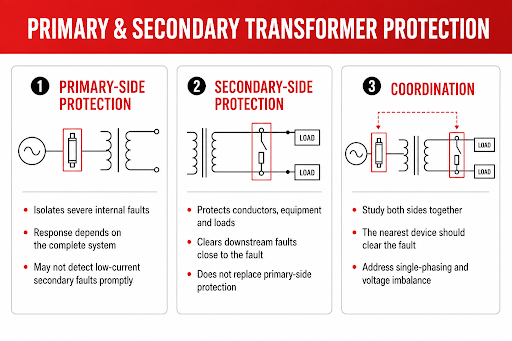
Primary-side fuses can disconnect the transformer from the source during severe internal faults and can limit exposure to some secondary through-faults. They may also protect the primary conductors when selected and installed for that purpose. Their view of a secondary fault is affected by the turns ratio, winding connection, grounding arrangement, fault type, and transformer impedance. A low-current secondary ground fault or overload may not produce enough primary current to operate an intentionally oversized primary fuse promptly.
Secondary protection is normally selected with the secondary conductors, distribution equipment, and connected loads in mind. It can clear downstream faults before the primary fuse opens and, in code-permitted arrangements, can contribute to transformer overload protection. It does not remove the need to evaluate internal transformer faults or the primary-side installation.
Coordination requires both sides to be studied together. A downstream fault should normally be cleared by the nearest device without unnecessarily opening the transformer primary. An internal fault must be isolated by devices capable of detecting and interrupting it. On a three-phase installation, one fuse opening also requires attention because sustained single-phasing or voltage imbalance may damage connected equipment without appropriate detection or isolation.
Select the Fuse by More Than its Ampere Rating
Two fuses with the same current rating can behave very differently. A complete selection considers voltage rating, continuous-current rating, interrupting rating, fuse class or medium-voltage type, time-current characteristic, current-limiting performance, and suitability for the equipment and installation.
A time-delay characteristic allows the fuse to tolerate a defined short-duration overcurrent, helping it ride through inrush while responding to sustained current. Operating time falls as current rises according to the fuse curve.
A current-limiting fuse operates rapidly when fault current enters its current-limiting range. It can reduce peak let-through current and I²t energy, lowering thermal and mechanical stress. The benefit is not automatic at every fault magnitude; published peak-current and energy data must support the evaluation. Time-delay and current-limiting are not mutually exclusive; one fuse may exhibit both properties.
The interrupting rating is a separate requirement. It is the maximum current the fuse is designed to interrupt at its rated voltage under specified conditions. It must not be confused with the ampere rating, which describes continuous carrying capability. A fuse that has an appropriate ampere rating but an inadequate interrupting rating is not suitable for the calculated fault duty.
Account for Transformer Impedance and Available Fault Current
Transformer percent impedance limits the current delivered into a secondary short circuit. As a first approximation, when upstream source impedance is neglected:
Isc = IFL ÷ Zpu
where Isc is symmetrical root-mean-square short-circuit current, IFL is full-load current, and Zpu is percent impedance divided by 100. Rex’s fault-current calculation guide explains the assumptions and limitations of this relationship.
Lower transformer impedance generally permits higher secondary fault current, raising the interrupting duty of fuses and equipment. Higher impedance reduces transformer contribution but may increase voltage drop. The study must use actual source, transformer, and conductor impedances rather than treating impedance as a fuse-selection value in isolation.
The study should consider maximum available fault current when verifying interrupting and equipment ratings. Minimum fault current also matters because it determines whether the intended device will operate quickly enough at the far end of a circuit or for a higher-impedance fault. System changes such as a larger utility service, a replacement transformer with different impedance, parallel sources, or on-site generation can invalidate an earlier result. Rex’s article on short-circuit withstand capability explains why both current magnitude and clearing time affect transformer stress.
Use Time-Current Curves to Verify Coordination
A coordination study plots device characteristics on a common time-current basis. It may include the inrush region, loading requirements, fuse and breaker curves, conductor damage limits, and transformer through-fault withstand. Currents and curves must be referred to the same side of the transformer before comparison.
Published fuse data may show minimum-melting and total-clearing curves. Selective coordination cannot be established by comparing ampere ratings alone; the applicable curves must remain separated over the required fault-current range.
IEEE C57.12.59-2015 addresses the application of overcurrent protective devices to limit dry-type transformer exposure to through-fault current. Importantly, the guide states that its through-fault recommendations are not intended to imply overload capability. This distinction reinforces why transformer fault withstand, overload protection, and conductor protection have to be checked as related but separate requirements.
Common Fuse-Sizing Errors
The most common error is selecting a fuse from full-load current alone. Others include assuming an inrush multiple instead of using transformer and fuse data; increasing fuse size after nuisance operation without identifying the event; checking only maximum fault current; or assuming a primary fuse fully protects secondary conductors and loads.
Substituting a different fuse solely because its ampere and voltage ratings match can also change the protection scheme. Fuse class, speed, current-limiting threshold, minimum-melting curve, total-clearing curve, and interrupting rating may differ. Replacement fuses should match the approved design and equipment instructions unless the protection study and equipment suitability are reassessed.
Finally, protective devices cannot compensate for an incorrectly specified transformer. Persistent overload, harmonic heating, inadequate ventilation, high ambient temperature, and unsuitable enclosure conditions must be addressed through load evaluation and transformer design. Rex’s transformer load-calculation guide covers the operating data needed before selecting transformer capacity. Protection should disconnect abnormal conditions; it should not be used to make an unsuitable duty appear acceptable.
Conclusion
Transformer fuse sizing is the process of coordinating load current, inrush, fault current, transformer withstand, conductor protection, and device operating characteristics. Full-load current establishes the starting point, but the final selection depends on the applicable code, transformer data, system study, fuse curves, and the intended division of protection between primary and secondary devices.
A well-coordinated scheme allows normal energization and permitted loading while clearing faults before damage escalates. It also isolates the smallest practical part of the system, reducing unnecessary outages without sacrificing transformer protection.
Transformer Impedance: What It Means for Fault Current, Voltage Regulation, and System Design
Updated: August 17th, 2026
A transformer with lower impedance may provide better voltage regulation. It may also deliver substantially more current into a downstream fault. Increasing the impedance can reduce that fault duty, but the same change may produce more voltage variation during motor starting or other high-current conditions.
This is why impedance should be considered during transformer sizing and selection, not treated as a nameplate value to review after the transformer has already been selected. It is part of the transformer’s electromagnetic design, and it affects the switchgear, conductors, protective devices, and connected loads around it.
Percent impedance, normally shown as %Z, describes the voltage required to circulate rated current through the transformer when one winding is short-circuited. That definition is straightforward. Its consequences for fault-current calculations, protection coordination, parallel operation, and transformer construction require a closer look.
What Percent Impedance Actually Represents
During a transformer short-circuit test, one winding is shorted, and a reduced voltage is applied to the other. The applied voltage is gradually increased until rated current flows through the windings.
If rated current is reached with 5.75% of rated voltage applied, the transformer has an impedance of 5.75%.
Under normal operation, the transformer transfers power magnetically from one winding to the other. During the short-circuit test, the low applied voltage produces only a small portion of normal core flux. The test is therefore dominated by the voltage required to overcome the winding resistance and leakage reactance at rated current.
Percent impedance expresses the combined internal impedance on the transformer’s own voltage and kVA base. This makes it useful in per-unit calculations and allows transformers with different ratings to be compared on a common basis. It does not mean that transformers of different sizes have the same impedance. The specified value still depends on the transformer’s rating, voltage class, construction, winding arrangement, and application.
The tested percent impedance is normally included with the other electrical ratings on the transformer nameplate. Rex’s transformer nameplate guide explains how to interpret these ratings and connection details.
Impedance Comes from Resistance and Leakage Reactance
Transformer impedance has two components: resistance and reactance.
Winding resistance is the electrical resistance of the conductors. It produces load loss and heat as current passes through the windings. The resistive component varies with conductor material, conductor cross-section, mean turn length, temperature, and connection arrangement.
Leakage reactance comes from magnetic flux that links one winding without fully linking the other. Unlike mutual flux in the core, this leakage field occupies the space within and around the windings. Its magnitude is strongly affected by winding height, radial build, spacing between windings, conductor arrangement, and the geometry of the leakage channel.
In many power and distribution transformers, leakage reactance accounts for most of the total impedance. This is an important distinction because it explains why a higher %Z does not automatically mean that the transformer has higher losses or lower efficiency. Two transformers can have similar impedance magnitudes but different resistance-to-reactance ratios and therefore different voltage-regulation, loss, and parallel-operation characteristics.
The relationship between these components is:

The total impedance shown on the nameplate gives the magnitude, but studies involving detailed voltage regulation, protection behaviour, or parallel operation may also require the resistance, reactance, or X/R ratio.
How Winding Design Controls Impedance
Leakage impedance is not a separate component installed inside the transformer. It is created by the winding arrangement itself.
Bringing the primary and secondary windings into closer electromagnetic coupling generally reduces leakage reactance. Increasing the distance between them generally increases it. The actual design is more involved because the engineer must also maintain dielectric clearances, provide cooling ducts, control mechanical forces, accommodate taps, and fit the winding assembly within the available core window.
These requirements often work against one another. A winding arrangement selected only for low impedance may not provide the required insulation distance or short-circuit strength. A design intended to increase impedance cannot simply add uncontrolled spacing without considering thermal performance, mechanical support, and the resulting dimensions.
This is also why impedance cannot normally be changed after manufacturing. Moving taps changes the effective turns ratio and operating voltage; it does not provide an adjustable impedance setting. If a system requires additional impedance after installation, it must generally be introduced through external equipment such as a current-limiting reactor or through a different transformer design.
The Direct Relationship Between Impedance and Fault Current
At the transformer secondary terminals, percent impedance provides a quick estimate of the symmetrical fault current the transformer can supply. If the available source is assumed to be infinitely strong and all external impedance is ignored, the approximate current is:
I_SC = I_rated × (100 ÷ Z%)
Where:
I_SC = short-circuit current
I_rated = transformer rated full-load current
Z% = transformer percent impedance
The same relationship can be written using per-unit impedance:
I_SC = I_rated ÷ Z_pu
The notation matters. A transformer with 5.75% impedance can be entered either as 5.75 in the first equation or as 0.0575 in the second. Mixing percentage and per-unit notation produces a result that is wrong by a factor of 100.
Consider a 500 kVA, three-phase transformer with a 480 V secondary and 5.75% impedance. Its rated secondary current is:
I_rated = (500 × 1,000) ÷ (√3 × 480) ≈ 601 A
The estimated symmetrical fault current at its secondary terminals is therefore:
I_SC = 601 × (100 ÷ 5.75) ≈ 10,450 A
The result is approximately 10.5 kA, assuming the transformer is the only impedance limiting the current.
If the same transformer had 4% impedance, the corresponding estimate would be approximately 15.0 kA. At 7% impedance, it would be approximately 8.6 kA. A change of only a few percentage points on the nameplate can therefore have a significant effect on the short-circuit duty imposed on downstream equipment.
This simplified calculation is useful for an initial check, but it is not a complete short-circuit study. The installed result also depends on utility or generator source impedance, upstream transformers, cables, busways, connections, and contributions from motors or other connected sources. Transformer impedance tolerances must also be considered when determining maximum possible fault current.
Lower Fault Current Is Not the Only Design Objective
It may appear desirable to specify higher impedance whenever available fault current is a concern. That decision has consequences elsewhere in the system.
As load current passes through the transformer impedance, an internal voltage drop develops. The magnitude and phase of that drop depend on the resistive and reactive components of the impedance and on the load power factor.
For a lagging power-factor load, approximate voltage regulation can be expressed as:
Voltage regulation ≈ R% cos φ + X% sin φ
where φ is the load power-factor angle; the reactive component becomes particularly important when the transformer supplies motors, welders, or other loads that draw substantial reactive current.
A higher-impedance transformer may therefore produce a deeper temporary voltage dip during motor starting or other sudden load changes. This can affect contactors, control circuits, variable-frequency drives, lighting, and sensitive electronic loads connected to the same bus.
The design decision is not simply “high impedance versus low impedance.” It is a balance among available fault current, voltage regulation, motor-starting performance, protective-device capability, physical construction, and the requirements of the connected load.
Impedance Sets the Starting Point for Protection Coordination
Protective devices can only clear faults correctly if the expected current lies within their operating and interrupting capabilities.
A low-impedance transformer may deliver enough current to operate an upstream or downstream device quickly, but it can also raise the fault duty beyond the interrupting rating of a breaker, fuse, switchboard, or panelboard. Higher transformer impedance reduces the available current, but sufficiently low fault current at a remote point may increase clearing time.
This is why protection coordination cannot be based on transformer full-load current alone. The study must consider maximum fault current for equipment-duty verification and minimum fault current for reliable protective-device operation. Conductor impedance, transformer tolerances, grounding arrangement, and the type and location of the fault can all change the result.
Specifying a different transformer impedance can sometimes help resolve a system fault-current limitation. It should not be used as a substitute for a complete coordination and equipment-rating review.
Why Impedance Matching Matters in Parallel Operation
Two transformers with the same voltage ratio do not necessarily share load equally when connected in parallel.
With compatible ratios, phase relationships, polarity, connections, and tap positions, the division of load is governed largely by their internal impedances. The transformer with the lower per-unit impedance tends to carry a greater share of the current. It can become overloaded before the combined bank reaches its apparent total kVA capacity.
Matching the magnitude of percent impedance is only part of the requirement. A significant difference in X/R ratio can cause the transformers to share real and reactive current differently, even when the impedance magnitudes appear close. Circulating current may also result from unequal secondary no-load voltages or incompatible tap positions.
Parallel operation should therefore be evaluated using the complete transformer data rather than a simple comparison of the two %Z nameplate values.
There Is No Universally Correct Impedance Value
Typical impedance varies with kVA rating, voltage class, winding construction, insulation requirements, and applicable product standards. Smaller low-voltage transformers may have relatively low impedance, while larger dry-type power transformers commonly require higher values. Special impedance levels may also be designed where an application has unusual fault-current, voltage-drop, or paralleling requirements.
These ranges should not be used as quality rankings. A transformer is not better because its impedance is lower, nor is it inherently safer because its impedance is higher. The relevant question is whether its impedance fits the electrical system in which it will operate.
The nameplate value or certified test report should always be used when calculating an existing unit. During specification, the required impedance should be established early enough for the transformer manufacturer to incorporate it into the winding design. Rex Power Magnetics can provide general-purpose isolation transformers with special impedance levels where the system requirements justify a non-standard design.
Conclusion
Transformer impedance connects the internal winding design to the behaviour of the entire electrical system. It determines how much fault current the transformer can supply, contributes to voltage variation under load, influences protective-device coordination, and controls how transformers divide load in parallel.
The lowest available impedance is not automatically the best choice. Neither is specifying a higher value simply to reduce fault current. Each change affects another part of the system.
The correct impedance is the value that satisfies the required balance among fault-current duty, voltage regulation, load behaviour, protection, and transformer construction. Establishing that balance before the transformer is manufactured is considerably easier than correcting it after the equipment and switchgear have been installed.
Transformers Design: How to Size and Select a Transformer
Transformer design is a foundational step in building reliable electrical power systems. Choosing the correct transformer size and configuration directly influences system performance, efficiency, safety, and long-term operating cost. While it may be tempting to focus only on voltage ratings and kVA, proper transformer design requires a broader understanding of how the transformer will be used, where it will be installed, and how it will operate over its lifetime.
Oversizing a transformer increases capital cost and no-load losses, while under sizing can lead to overheating, insulation degradation, and premature failure. Effective transformer design strikes a balance between electrical demand, thermal performance, and environmental conditions. This article outlines the key engineering principles that guide proper transformer sizing and selection in real-world applications.
Understanding the Load
Every transformer design begins with the load it is intended to supply. Simply adding up connected equipment ratings rarely provides an accurate picture of actual operating demand. In most systems, loads vary over time, and not all equipment operates simultaneously.
Engineers must evaluate whether the load is continuous or intermittent, whether demand fluctuates significantly, and whether future expansion is likely. Load diversity, duty cycle, and operational patterns all influence transformer thermal loading. A transformer designed solely for connected load may be oversized, while one designed without considering continuous duty may operate beyond its thermal limits.
Accurate load definition ensures the transformer is neither overstressed nor unnecessarily oversized.
Selecting the Appropriate kVA Rating
The kVA rating of a transformer represents its ability to carry load continuously without exceeding allowable temperature rise. This is fundamentally a thermal consideration rather than a purely electrical one.
When selecting kVA, designers must consider how heavily and how often the transformer will be loaded. A transformer operating near full load continuously experiences significantly more thermal stress than one operating intermittently. In applications with cyclical loading or known overload conditions, additional margin may be justified. However, excessive oversizing should be avoided, as lightly loaded transformers incur higher core losses and reduced operating efficiency.
Proper kVA selection balances thermal capability, efficiency, and lifecycle cost.
Voltage Levels and System Configuration
Transformer voltage selection must align with both the supply system and downstream utilization equipment. Primary voltage must accommodate supply tolerances, while secondary voltage must meet equipment requirements under normal and loaded conditions.
Designers must also determine whether the application requires a step-up or step-down transformer and whether a single-phase or three-phase unit is appropriate. Winding configuration plays a critical role in system behavior. Wye-connected secondaries provide a neutral and support grounded systems, while delta connections offer isolation and block zero-sequence currents. More specialized configurations, such as zig-zag windings, are used for grounding or harmonic mitigation.
These decisions influence grounding, protection coordination, fault behavior, and overall system stability.
Accounting for Harmonic Loads
Modern electrical systems increasingly serve non-linear loads such as variable-frequency drives, data centre equipment, UPS systems, and electronic lighting. These loads introduce harmonic currents that increase transformer heating beyond what would be expected from RMS current alone.
Harmonics raise conductor and stray losses, increase neutral currents, and elevate winding hot-spot temperatures. If not considered during design, they can significantly shorten insulation life. In systems with substantial non-linear loading, standard transformers may require increased capacity, enhanced insulation systems, or specialized designs such as K-rated or harmonic-mitigating transformers.
Harmonic assessment is therefore an essential part of transformer sizing and selection in contemporary power systems.
Insulation System and Thermal Design
The insulation system defines the maximum allowable winding temperature and directly affects transformer life expectancy. Insulation class, ambient temperature, and temperature rise work together to determine thermal margin.
Using a higher insulation class while operating at a lower temperature rise can extend insulation life and improve reliability. This approach also provides flexibility to accommodate higher-than-expected ambient temperatures, altitude-related cooling limitations, or additional heating from harmonic currents. Insulation selection is not simply a material choice; it is a strategic design decision that influences long-term performance.
Cooling Method and Duty Cycle
Transformer cooling determines how effectively heat is removed from the windings and core. Natural air cooling is sufficient for many applications, but forced-air cooling may be required where space is limited or where higher load capacity is needed without increasing physical size.
The duty cycle of the load also matters. Transformers serving intermittent or cyclic loads may benefit from forced-air cooling during peak demand while operating naturally during normal conditions. Cooling selection allows designers to optimize transformer size without compromising thermal performance.

Environmental and Installation Considerations
The installation environment has a major impact on transformer selection. Indoor installations with controlled conditions place fewer demands on insulation systems than outdoor or industrial environments exposed to moisture, dust, or corrosive atmospheres.
VPI and VPE dry-type transformers perform well in clean, controlled indoor spaces, while cast coil transformers offer superior resistance to environmental contaminants and mechanical stress. Ambient temperature extremes, altitude, ventilation constraints, and noise requirements must all be considered during design. A transformer well-suited for one environment may perform poorly in another if these factors are ignored.
Impedance, Fault Levels, and System Performance
Transformer impedance influences both fault current and voltage regulation. Higher impedance limits short-circuit current, which can reduce stress on downstream equipment and simplify protection coordination. However, excessive impedance can result in unacceptable voltage drop under load.
Impedance selection must balance fault-current limitation with system performance requirements. It also affects parallel operation, where impedance matching is essential for proper load sharing between transformers.
Efficiency and Losses
Transformer efficiency depends on both core losses, which occur whenever the transformer is energized, and load losses, which increase with current. The most efficient transformer for a given application depends on its typical loading profile rather than peak load alone.
In many installations, a transformer operates well below full load for most of its life. In such cases, lower core losses may provide greater lifecycle savings than marginal improvements in full-load efficiency. Evaluating losses in the context of expected operating conditions leads to better long-term economic outcomes.
Common Design Pitfalls
Many transformer issues arise not from manufacturing defects, but from design oversights. Common problems include neglecting harmonic loading, oversizing without justification, incorrect voltage assumptions, and failure to consider ambient conditions or future expansion. Addressing these issues early in the design process significantly improves reliability and reduces operating cost.
Conclusion
Transformer design is a balance of electrical, thermal, and environmental considerations. Proper sizing and selection require more than matching nameplate values; they demand an understanding of how the transformer will operate throughout its life. By carefully evaluating load behavior, harmonic content, insulation systems, cooling methods, and installation conditions, engineers can select transformers that deliver reliable performance, efficient operation, and long service life.
Cast Coil Transformers: Reliable and Durable Solutions for Modern Power Systems
Cast coil transformers — also known as cast resin dry-type transformers — have become a preferred solution for modern power systems that demand high reliability, environmental durability, and reduced maintenance. Compared with traditional liquid-filled and VPI/VPE dry-type units, cast coil transformers offer exceptional mechanical strength, enhanced insulation robustness, and strong resistance to moisture, dust, and chemical contaminants.
These characteristics make cast coil technology ideal for commercial buildings, industrial plants, data centres, and other facilities where uptime and environmental resilience are critical. This article explains what cast coil transformers are, how they are manufactured, where they are used, and why they offer a dependable choice for today’s electrical infrastructure.
What Is a Cast Coil Transformer?
A cast coil transformer uses epoxy resin encapsulation to insulate and protect the windings—most commonly the high-voltage winding. During manufacturing, the coils are cast under vacuum using a controlled epoxy resin system that forms a rigid, solid structure around the conductors.
This encapsulation provides several benefits:
- Exceptional dielectric strength
- High resistance to moisture and corrosion
- Mechanical rigidity and vibration tolerance
- Reduced risk of partial discharge or surface tracking
Comparison with VPI and VPE
Although VPI (Vacuum Pressure Impregnation) and VPE (Vacuum Pressure Encapsulation) dry-type transformers also use resin-based insulation systems, they differ significantly from cast coil construction:

VPI/VPE: Windings are impregnated with resin but remain largely open to air.
Cast Coil: Windings are fully encapsulated in solid epoxy, creating a robust, sealed insulation structure.
Cast coil transformers typically use Class H (180°C) insulation systems, providing high thermal strength and excellent performance in demanding applications.
Manufacturing Process of Cast Coil Transformers
Cast coil manufacturing involves several steps designed to produce a mechanically strong and electrically reliable product.
Winding Formation: Conductors are wound onto formers with precise layering to minimize electrical stresses.
Preheating: Coils are preheated to remove moisture and ensure proper resin adhesion.
Vacuum Casting: Epoxy resin is introduced under vacuum and sometimes under pressure to eliminate air pockets and achieve full encapsulation.
Curing: The cast coil undergoes a controlled thermal cure, forming a rigid, homogeneous insulation structure.
Final Assembly: The finished coils are mounted with the core, interconnections are made, and the transformer is assembled into its enclosure or frame.
This process yields a winding system with extremely high short-circuit strength, excellent moisture resistance, and reliable long-term thermal performance.
Applications for Cast Coil Transformers
Because of their rugged construction and environmental tolerance, cast coil transformers are well-suited for:
- Commercial high-rises where fire safety and reliability are essential
- Industrial plants exposed to dust, humidity, or chemical contaminants
- Data centres requiring stable operation and minimal downtime
- Mines and heavy industrial operations with vibration or harsh ambient conditions
- Water treatment facilities exposed to moisture and corrosive atmospheres
- Marine and offshore platforms
- Renewable energy installations, such as wind turbine towers or solar farms
Engineers often choose cast coil units when environmental robustness outweighs cost considerations or when the operational environment poses risks to conventional dry-type insulation systems.
Key Advantages of Cast Coil Transformers
Mechanical and Thermal Durability
The epoxy encapsulation provides excellent resistance to short-circuit forces, vibration, and thermal cycling. The solid insulation structure minimizes partial discharge and enhances dielectric reliability.
Environmental Resistance
Cast coils are highly resistant to humidity, salt spray, dust, industrial vapours, and airborne contaminants. This makes them ideal for indoor or outdoor installations, including corrosive or high-contaminant environments.
Fire Safety
Epoxy insulation is inherently flame-retardant and self-extinguishing. Cast coils generate reduced smoke and toxic gases compared to some other insulation systems, supporting safer operation in enclosed or public spaces.
Low Maintenance
With no oil to test or replace—and no risk of leaks—cast coil transformers require minimal routine maintenance. The sealed insulation system resists contamination and does not require periodic varnish or insulation refresh.
Reliable Operation in Critical Applications
Cast coil transformers maintain performance under heavy loading, harmonic conditions, and thermal stress. Their mechanical strength and environmental durability support long service life and dependable operation.
Cast Coil vs. VPI/VPE Dry-Type Transformers
Both technologies have valid use cases, but cast coil excels in harsher environments and applications requiring maximum reliability.

General-purpose applications

In many situations, VPI/VPE transformers offer a cost-effective and reliable option. However, when the installation environment includes moisture, dust, vibration, or industrial contaminants, cast coil technology often provides the superior long-term solution.
Design Considerations for Cast Coil Transformers
Selecting or specifying a cast coil transformer requires consideration of:
- Thermal class and temperature rise
- Partial discharge performance and insulation integrity
- Short-circuit withstand ratings
- Cooling options (natural air or forced air for increased kVA)
- Core selection and flux density optimization
- Harmonic loading suitability, including K-factor considerations when needed
- Environmental conditions, including altitude, temperature, and enclosure type
Cast coil transformers are often chosen when additional mechanical protection or environmental sealing is necessary.
Rex Power Magnetics Perspective
Rex Power Magnetics designs and manufactures high-quality cast coil transformers for power distribution and industrial applications. Our cast coil products incorporate:
- Class H insulation systems as standard
- High mechanical strength for short-circuit and vibration durability
- Advanced winding and casting processes that minimize partial discharge
- Optional forced-air cooling for increased capacity
- Engineering support for harmonic loading, environmental challenges, and application-specific requirements
Rex cast coil transformers are deployed in mission-critical, high-reliability environments across North America and internationally.
Conclusion
Cast coil transformers offer a highly reliable, durable, and low-maintenance solution for modern power systems. Their epoxy encapsulated windings provide exceptional mechanical strength, environmental resistance, and fire safety—making them ideal for demanding commercial, industrial, and infrastructural applications.
As electrical systems continue to evolve and environments become more challenging, cast coil technology remains a proven and resilient choice for engineers seeking long-term performance and reliability.
Transformer Grounding: Understanding the Importance of Proper Transformer Neutral Grounding
Transformer grounding is one of the most critical aspects of electrical system design. It establishes a reference point for phase voltages, ensures predictable system behavior during ground faults, and enables safe operation of protection systems. Whether applied in commercial, industrial, or utility environments, proper transformer neutral grounding is fundamental to electrical safety, equipment performance, and compliance with local electrical codes.
Grounding practices vary depending on transformer configuration, system voltage, and the nature of the loads being supplied. In all cases, however, grounding must follow the requirements of the Canadian Electrical Code (CEC) or the National Electrical Code (NEC), along with manufacturer recommendations. Improper grounding can lead to unstable voltages, nuisance tripping, dangerous overvoltages, or even catastrophic equipment failures.
This article explains what transformer neutral grounding is, why it is essential, and how different grounding methods affect system performance.
What Is Transformer Neutral Grounding?
Transformer neutral grounding refers to the intentional connection of a transformer’s neutral point—typically on the secondary winding—to ground. This connection establishes a stable reference for the electrical system and defines how the system responds to ground faults.
A transformer secondary is considered a separately derived system (SDS) when it is electrically isolated from all other grounded systems. When a transformer creates an SDS, the system neutral must be grounded according to code-defined rules. This grounding point also dictates where the system’s neutral-to-ground bond is permitted.
Neutral grounding is more than a simple bond. It determines:
How ground faults flow
- What voltage stresses the insulation experiences
- How protective relays and circuit breakers operate
- Whether touch voltages remain safe under fault conditions
Proper grounding is therefore not optional; it is a critical engineering decision.
Why Proper Grounding Is Essential
Grounding directly affects four key aspects of electrical system performance.
Safety
Grounding prevents phase-to-ground voltages from drifting upward, thereby reducing shock hazards. It also ensures that ground-fault currents return through a controlled path rather than through unintended structures or personnel.
Protection System Performance
Protective devices rely on ground-fault current magnitude and direction. Proper grounding ensures that:
- Fault currents are high enough for relays to detect
- Protection settings coordinate correctly
- Ground faults clear rapidly and selectively
Without grounding, fault currents may be too low for protective devices to respond.
Voltage Stabilization
Grounding helps maintain stable phase-to-ground voltage relationships. Systems without proper grounding may experience floating neutral conditions, transient overvoltages, or ferroresonance—each of which can impose severe stress on insulation systems.
Equipment Longevity
Ungrounded or improperly grounded systems can subject equipment to unpredictable voltage stress, increasing the risk of premature insulation failure or transformer damage.
Types of Transformer Grounding Configurations
Different grounding methods define how the system behaves during a ground fault.
1. Solidly Grounded Systems
The neutral is directly bonded to ground.
- Fast operation of protection systems
- High ground-fault currents
- Common for low-voltage distribution (e.g., 208Y/120 V, 480Y/277 V systems)
2. Resistance Grounded Systems
The neutral is connected to ground through a resistor.
- Limits fault current to safer levels
- Reduces mechanical and thermal stress
- Widely used in medium-voltage industrial systems
3. Reactance Grounded Systems
The neutral is grounded through a reactor (air-core).
- Limits fault current using inductive reactance
- Used in MV/HV networks and generator applications
- Provides controlled fault levels while preventing transient overvoltages
4. Ungrounded Systems
No intentional connection to ground.
- Allows continued operation during the first ground fault
- Higher risk of transient overvoltages
- Rarely used in modern design except in specialized industrial applications
- Transformer Winding Configurations and Grounding Implications
- Transformer winding configuration determines whether a natural neutral point is available.
Wye (Star) Secondary
A wye-connected secondary provides a natural neutral point.
- Ideal for 4-wire distribution systems
- Simple, reliable grounding
- Used for 208Y/120 V, 600Y/347 V, and similar systems
- Delta Secondary
Delta windings have no neutral point.
- Cannot supply line-to-neutral loads
- Provide isolation from upstream grounding
- Often used for motor loads or to block triplen harmonics
If grounding is required, it must be achieved using a grounding transformer.
Zig-Zag and Grounding Transformers
These special-purpose transformers create a neutral point for grounding when none exists on the system. They are commonly used:
- On delta-fed systems requiring a neutral for grounding
- In grounding resistor/reactor applications
- In systems requiring harmonic reduction from zero-sequence currents
- Grounding Transformers: When the Neutral Is Not Available
A grounding transformer is used to supply a neutral reference when the main transformer’s secondary does not provide one. This is necessary for:
- Delta-only systems needing ground-fault protection
- Distributed generation installations requiring defined grounding
- Systems where ground-fault currents must be limited
Zig-zag grounding transformers and wye-broken-delta connections are the most common configurations. They provide an effective neutral point while controlling the magnitude and path of ground-fault current.
Consequences of Improper or Missing Neutral Grounding
Improper grounding can create severe operational and safety issues, including:
- Unstable phase voltages due to floating neutral conditions
- Nuisance tripping or failure of ground-fault protection
- Elevated insulation stress, leading to premature equipment failure
- Transient overvoltages that exceed transformer BIL ratings
- Difficult fault location, prolonging unsafe conditions
- Circulating currents, if multiple neutral-ground bonds exist
- Shock hazards, due to unregulated touch/step voltages
In extreme cases, improper grounding can lead to catastrophic equipment failure.
Code Requirements (CEC and NEC)
Both the CEC and NEC define when and how transformer secondaries must be grounded. While specific clauses differ, both codes require:
- Grounding of secondary neutrals in most SDS configurations
- A single neutral-to-ground bond per SDS
- Proper sizing of grounding electrodes, bonding jumpers, and grounding conductors
- Clear identification of grounding conductors
- Ground-fault protection where required
Adhering to code requirements is not only mandatory for inspection approval but also essential for safe operation.
Best Practices for Transformer Neutral Grounding
Good engineering practice strengthens both safety and system reliability.
- Confirm whether the transformer secondary forms a separately derived system (SDS).
- Ground the neutral at the location specified by code—usually the first disconnecting means.
- Ensure only one neutral-to-ground bond exists within the SDS.
- Size grounding and bonding conductors according to the available fault current.
- Coordinate grounding method with protective device settings.
- For harmonic-heavy installations, evaluate neutral conductor loading and consider oversized neutrals or grounding transformers.
- When using resistance or reactance grounding, verify thermal and short-time ratings for the grounding equipment.
Rex Power Magnetics Perspective
Rex Power Magnetics provides transformers designed with grounding in mind. Our capabilities include:
- Wye, delta, zig-zag, and grounding transformer designs
- Compatibility with resistance and reactance grounding systems
- Engineering guidance for grounding, bonding, and SDS configuration
- Application support for harmonic mitigation and neutral loading
- Clear documentation and diagrams for correct grounding and installation
By combining engineering expertise with high-quality manufacturing, Rex ensures that customers receive safe, reliable, and code-compliant grounding solutions.
Conclusion
Proper transformer neutral grounding is essential for ensuring electrical safety, stable phase voltages, predictable protection behavior, and long equipment life. Grounding choices directly affect system performance during faults and must be selected carefully based on transformer configuration, system requirements, and code rules.
By understanding the grounding implications of transformer winding arrangements and applying appropriate grounding methods—whether solid, resistive, or reactive—engineers can create electrical systems that operate safely, efficiently, and reliably.
Neutral Grounding Reactors: Ensuring Safe Ground Fault Protection
Grounding is a foundational aspect of power system design. It stabilizes phase voltages, provides a reference point for protection systems, and ensures that ground faults are managed safely and predictably. Among the available grounding methods, Neutral Grounding Reactors (NGRs) are widely used in medium and high-voltage networks to limit ground-fault current to controlled levels without the drawbacks associated with solid grounding or ungrounded systems.
A neutral grounding reactor introduces inductive reactance into the neutral-to-ground connection, ensuring that ground-fault currents remain high enough for detection but low enough to prevent equipment damage. This article explains how NGRs function, where they are applied, and why air-core construction is required for their safe and reliable performance.
Why Controlled Grounding Matters
Ground faults are the most common type of electrical fault. When a system is solidly grounded, these faults can result in extremely high fault currents, leading to:
- Thermal and mechanical stress on transformers, cables, and switchgear
- Increased arc-flash energy
- Greater likelihood of equipment failure
- Voltage depression on unfaulted phases
Conversely, ungrounded systems experience:
- Transient overvoltages
- Difficulty locating ground faults
- Insulation stress and potential resonance issues
Neutral grounding reactors offer a balanced solution. They limit ground-fault current to a safe level that still enables protective relays to operate reliably. As a result, they improve system safety, enhance coordination, and reduce damage during faults.
What Is a Neutral Grounding Reactor?
A Neutral Grounding Reactor (NGR) is an air-core inductor installed between a system’s neutral and ground. Its inductive impedance controls the magnitude of zero-sequence current that flows during a ground fault.
Why Neutral Grounding Reactors Must Be Air-Core
Neutral grounding reactors are never built with iron cores, and this is fundamental to their operation. During a ground fault, current can rise to hundreds or thousands of amperes within milliseconds. An iron-core inductor would saturate almost immediately, causing its inductance to collapse. This would eliminate its ability to limit fault current and could create unpredictable system behavior.
Air-core reactors avoid this problem entirely because:
- They cannot saturate, maintaining stable inductance even at high fault currents.
- Their behavior remains linear, which is essential for protection coordination.
- They provide predictable fault-current limitation, allowing protection settings to be designed accurately.
- They avoid the nonlinear distortion, magnetic losses, and heating associated with iron-core saturation.
For grounding applications—where performance must remain stable over a wide fault-current range—air-core construction is the only technically acceptable choice.
How Neutral Grounding Reactors Work
Normal Operation
During balanced conditions, no current flows through the reactor. It has no effect on system voltage, load capacity, or efficiency.
Ground-Fault Operation
When a ground fault occurs:
- Zero-sequence current attempts to flow to ground.
- The reactor introduces inductive impedance in this path.
- Fault current is limited to a controlled value (typically 100 A to several kA).
- Protective relays detect and isolate the fault.
Because the reactor is air-core, it maintains a predictable impedance throughout the fault, ensuring reliable operation of protection devices.
Voltage Stability
NGRs help stabilize the phase-to-ground voltages on unfaulted phases, reducing the overvoltages common in ungrounded systems and improving insulation reliability.
Applications for Neutral Grounding Reactors
Neutral grounding reactors are widely used in:
- Medium-voltage industrial systems (5 kV–35 kV)
- Generator grounding, providing controlled fault current for large rotating machines
- Utility distribution feeders
- Mining, petrochemical, pulp and paper, and heavy industrial facilities
These systems benefit from a controlled response to ground faults and improved protection selectivity.
Benefits of Neutral Grounding Reactors
Neutral grounding reactors offer several significant operational advantages:
Improved Fault Safety
By limiting fault current, NGRs lower the mechanical and thermal stress on equipment and reduce arc-flash energy.
Reliable Protection Coordination
With predictable fault-current levels, relay coordination becomes more stable and effective.
Reduced Equipment Stress
Cables, switchgear, and transformers experience lower fault-induced forces and temperatures.
Voltage Stabilization
NGRs maintain more consistent phase-to-ground voltage relationships during faults.
Operational Continuity
Depending on system philosophy, facilities may continue operating through a ground fault long enough for controlled shutdown or isolation.
Neutral Grounding Reactors vs. Neutral Grounding Resistors
A comparison often arises between resistive and reactive grounding:
Reactors are preferred where inductive limitation better aligns with protection philosophy and system behavior.

Design Considerations for Selecting an NGR
Selecting a neutral grounding reactor requires attention to both system requirements and reactor characteristics:
- System voltage and BIL rating
- Required ground-fault current limit
- Zero-sequence network impedance
- Air-core construction for linear, non-saturating performance
- Thermal and mechanical fault rating (e.g., 10-second duty)
- Installation location (indoor/outdoor)
- Enclosure type, cooling, and clearance requirements
Air-core reactors ensure stable performance during the entire fault period, which is why they remain the industry standard for grounding applications.
Rex Power Magnetics Perspective
Rex Power Magnetics designs and manufactures air-core neutral grounding reactors tailored to system parameters and protection requirements. Our capabilities include:
- Custom impedance design for controlled ground-fault current
- Generator grounding reactors
- Outdoor-rated or indoor-enclosed assemblies
- System-level grounding solutions including grounding transformers
- Engineering support for grounding philosophy, protection coordination, and application review
Our reactors are engineered to provide reliable, predictable performance in demanding industrial and utility environments.
Conclusion
Neutral grounding reactors provide a safe and effective method of controlling ground-fault current in medium and high-voltage systems. By using air-core construction, they deliver stable, non-saturating inductive impedance that ensures predictable protection behavior, reduces equipment stress, and improves voltage stability during ground faults.
For facilities and utilities seeking to balance safety, reliability, and protection performance, NGRs offer a proven and technically robust grounding solution.