Mini Power Centers Explained: When Integrated Distribution Makes Sense
Most low-voltage distribution gets built up from discrete components. A transformer here, a primary disconnect there, a panelboard somewhere downstream, conduit and conductors tying them together, all sized and specified and installed separately. For the majority of commercial and industrial applications, that’s the right approach — flexible, well-understood, and built around the standard equipment electricians work with every day.
There’s a class of installations where the discrete approach starts to lose its advantages. Tight spaces, remote locations, repeated identical drops to the same kind of load, or budgets and schedules that can’t absorb the labor of assembling and coordinating multiple components on site. For those cases, the mini power center (MPC) packages the same functions into a single factory-assembled unit. This article covers what an MPC actually is, where it fits, and how to think about the choice between integrated and discrete distribution.
What a Mini Power Center Actually Is
A mini power center is a single enclosure that integrates the three main components of a small distribution drop:
- Primary disconnect — a fused switch or circuit breaker on the input side
- Step-down transformer — typically 480 V or 600 V primary to 120/240 V or 208/120 V secondary encapsulated transformer
- Secondary panelboard — with branch circuit breakers and a neutral/ground bus
Everything is factory-wired, tested, and labeled. The installation reduces to mounting the enclosure, landing the primary feed, and landing the branch circuits. The transformer is usually a dry-type encapsulated or ventilated design, sized in the range of 5 to 75 kVA for most product lines.
What sets MPCs apart from a “small substation” or “unit substation” is the scale and the application focus. Unit substations handle hundreds to thousands of kVA at medium voltage. Mini power centers handle the tail end of low-voltage distribution — the last step from a facility bus down to receptacle or lighting voltage at a specific load location.
Where MPCs Earn Their Place
A few application patterns repeat in the field.
Remote or distributed equipment. Pumping stations, telecom huts, EV charging sites, outdoor process equipment, modular buildings, and similar installations often need a small panel of 120 V circuits, fed from a 480 V or 600 V supply that’s already on site. Running an entire transformer-plus-panelboard assembly to each location adds labor, coordination, and on-site rework. An MPC arrives ready to wire.
Repeated identical drops. When a facility has a dozen identical workstations, machine tools, or equipment skids, each requiring the same modest amount of utilization voltage, an MPC at each location is faster to specify, easier to standardize, and simpler to maintain than a dozen custom assemblies.
Space-constrained installations. A factory-integrated unit takes less floor space than discrete components with conduit between them, and the layout is fixed in advance. In mechanical rooms, electrical closets, and modular installations where every inch matters, an MPC can fit where a discrete assembly doesn’t.
OEM and skid-mounted equipment. Equipment manufacturers building skids for delivery to end users frequently spec MPCs as the supply for onboard controls and auxiliaries. The skid arrives at the customer site with one primary connection and a fully integrated secondary distribution.
Temporary and rental power. Construction sites, events, and temporary installations benefit from the rapid deployment that integrated equipment allows. Plug-and-play primary connection, immediate availability of branch circuits.
MPC vs. Discrete Distribution: The Real Trade-Offs
The decision between an MPC and a discrete transformer-plus-panelboard setup comes down to a small number of factors. Both approaches deliver the same end result — isolated, properly fused branch circuits at the required voltage — but the cost and complexity profile differs.
Installation labor. MPCs win, often by a lot. A discrete assembly involves mounting the transformer, mounting the primary disconnect, mounting the panelboard, sizing and pulling conduit between them, terminating the inter-component wiring, and labeling everything. An MPC arrives with all of that done. For a small installation with one feed and one panel, the labor savings frequently exceed the equipment cost difference.
Equipment cost. Discrete components are usually cheaper to buy in isolation. Buy a transformer, a disconnect, and a panelboard separately and the bill of materials is typically lower than the equivalent MPC. The MPC’s premium pays for the factory integration, the testing, and the single-source warranty. Whether that premium is worth it depends on the labor and coordination savings on the other side.
Flexibility. Discrete wins. A standard MPC comes with a fixed transformer kVA, a fixed number of branch circuit poles, and a fixed enclosure configuration. If the application later needs more capacity, more circuits, or different protection, modifying an MPC is harder than swapping a component in a discrete assembly. Discrete construction also accommodates non-standard requirements — unusual voltages, special transformer types (K-factor, drive isolation, harmonic-mitigating), or unusual breaker arrangements — that an off-the-shelf MPC may not.
Footprint. MPCs win. Factory integration removes the conduit between components and packs the assembly tighter than discrete construction usually achieves.
Maintenance. Roughly even, with different failure modes. An MPC consolidates several components in one enclosure, so a transformer fault that takes the unit out of service may require pulling the entire MPC. A discrete assembly lets you replace a panelboard without touching the transformer. On the other hand, MPCs come with a single source of warranty and support, which can simplify troubleshooting on critical installations.
Standardization. MPCs win for repeated installations. Specifying one part number twelve times is much easier than coordinating twelve discrete assemblies. The downside is that the standardization only helps if the application actually fits the standard product.
Sizing and Specification
MPC sizing follows the same logic as any other transformer-and-panel combination. The kVA must cover the connected load with appropriate diversity, plus margin for inrush, harmonics, future growth, and ambient conditions. A standard rule of thumb — size the transformer to 80% loading at expected peak, then verify against the actual harmonic and inrush profile — works reasonably well for typical commercial and light industrial loads. For loads with significant power-electronic content (LED drivers, VFDs, electronic ballasts, switching power supplies), a K-factor rated transformer or explicit harmonic margin is appropriate.
Voltage selection is usually constrained by what’s available on site. A 480 V three-phase primary feeding a 208Y/120 V secondary is the most common configuration in North American commercial work. 600 V primaries are common in Canadian installations. 240 V primaries serve light commercial or residential adjacent applications.
Panelboard sizing — number of poles, main breaker rating, branch breaker provisions — should be matched to both immediate needs and reasonable future expansion. Specifying too tightly is a common error; the cost difference between a 12-circuit and an 18-circuit MPC is usually small compared to the cost of replacing the entire unit when the building load grows.
Other selection considerations include enclosure rating (NEMA 1 indoor, NEMA 3R outdoor, NEMA 4X for washdown or corrosive environments), grounding configuration, fusing or breaker preference on the primary, and any specific listings or certifications required for the installation (CSA, UL, NEMA, or industry-specific).
When to Skip the MPC
A few application patterns push back toward discrete components.
Large installations. Above a few hundred amperes on the secondary, the integrated form factor stops making sense and a unit substation or discrete construction is more appropriate.
Unusual voltages or special transformers. If the application needs an isolation transformer with electrostatic shielding, a K-13 or K-20 harmonic-rated unit, a drive isolation transformer, or any non-standard voltage ratio, an off-the-shelf MPC may not cover it. Custom MPC construction is possible but starts to erode the cost advantage.
Frequent reconfiguration. Installations where the panel layout, circuit count, or transformer size is likely to change significantly over time are better served by discrete components that can be modified piece by piece.
Highly critical loads with specific maintenance requirements. Applications where individual components need to be serviced or replaced without affecting the others may justify the labor cost of discrete construction.
Conclusion
Mini power centers solve a specific problem: getting from a facility bus to usable utilization voltage at a load location, with minimum installation labor, predictable footprint, and standardized specifications. They’re not a replacement for discrete distribution in general — they’re the right tool for the applications where their advantages line up with the actual requirements.
The choice between integrated and discrete distribution isn’t a value judgment about either approach. It’s a question of which one fits the constraints of the specific installation. Remote, repeated, space-constrained, or skid-mounted applications usually point toward an MPC. Large, custom, evolving, or specialty applications usually point toward discrete components. Most facilities end up with both, used where each makes the most sense.
How Transformers Work: Working Principle, Components, and System Role
Transformers are everywhere in the electrical grid, yet most people who specify, install, or work near them rarely think about how they actually function. The principle is over a century old and conceptually simple. The implications for system design are not.
Understanding what a transformer does — and, just as importantly, what it cannot do — is the foundation for nearly every voltage decision in a power system, from utility transmission down to the panelboard in a mechanical room. This article walks through the working principle, the components that make it practical, and the role transformers play at each stage of the power system.
What a Transformer Does
A transformer transfers electrical energy between two circuits through a magnetic field, while changing the voltage level. The frequency stays the same. There is no direct electrical connection between the input and output sides — energy crosses the gap through magnetic coupling alone.
That single property is what makes the modern grid possible. It allows voltage to be raised for efficient transmission and lowered for safe use, and it provides electrical isolation between circuits as a side effect.
In facility and industrial systems, transformers operate within low and medium voltage ranges, typically supporting distribution rather than transmission. Dry-type construction is common in these environments because it works well indoors and integrates cleanly into building electrical systems.
The Working Principle
Transformer operation is based on electromagnetic induction.
When alternating current flows through the primary winding, it creates a time-varying magnetic field in the core. That changing flux passes through the secondary winding and induces a voltage across it. Connect a load to the secondary, and current flows.
The sequence is straightforward:
Input voltage → current in the primary winding → changing magnetic field in the core → induced voltage in the secondary winding → output to the load
Energy moves through the magnetic field, not through a wire between the two sides. That distinction is the reason transformers also provide galvanic isolation — a useful property that gets exploited deliberately in some applications.
Why Transformers Need AC
Induction depends on a changing magnetic field. With direct current, the field becomes static after the initial energization, no further voltage is induced, and the transformer stops doing useful work.
This is why conventional transformers operate only on alternating current. Modern DC systems — solar arrays, battery storage, HVDC links — handle this through power-electronic conversion stages that produce AC at the transformer interface. The transformer itself doesn’t change.
How Voltage Transformation Works
The voltage ratio between primary and secondary is set by the turns ratio: more turns on the secondary produces higher voltage, fewer turns produces lower voltage.
Voltage and current move in opposite directions for a given power level. When voltage doubles, current halves. This inverse relationship is the entire reason high-voltage transmission exists — lower current means lower I²R losses in the conductors, which means power can travel further without wasting itself as heat in the wires.
A transformer doesn’t create energy. It trades voltage for current, or current for voltage, with a small fraction lost as heat in the core and windings.
Core Components
The principle is simple. Making it work efficiently at scale is where the engineering lives.
Magnetic core. Provides a controlled path for magnetic flux. Built from thin laminated steel sheets to reduce eddy-current losses, with grain-oriented silicon steel common in higher-efficiency designs.
Primary and secondary windings. Conductive coils — usually copper or aluminum — that carry the current and set the turns ratio. Conductor sizing, geometry, and insulation between layers all influence performance.
Insulation system. Separates the windings from each other and from the core. Dry-type transformers use solid insulation and air; liquid-filled transformers use oil or other dielectric fluid. The insulation system is often what determines the transformer’s voltage class and thermal rating.
Cooling system. Transformer losses turn into heat, and that heat has to go somewhere. Dry-type designs use natural or forced air (AN or AF). Without adequate cooling, insulation degrades and service life drops sharply.
Where Transformers Sit in the Power System
| Stage | Voltage Range | Transformer Role |
|---|---|---|
| Generation | Moderate generator voltage (typically 13.8–25 kV) | Step up to transmission voltage at the plant |
| Transmission | 115 kV to 765 kV | Long-distance transport at high voltage to minimize losses |
| Sub-transmission | 35 kV to 138 kV | Step down between transmission and regional distribution |
| Primary distribution | 4 kV to 35 kV | Step down to feed neighborhoods, campuses, industrial sites |
| Secondary distribution / facility | 208 V to 600 V | Step down to utilization voltage for buildings and equipment |
| End use / specialty | Varies | Isolation, voltage matching, distributed energy interconnection |
At each transition, a transformer does the same fundamental job — changes the voltage level — but the specification, construction, and protection requirements differ significantly across the stages.
Categories Used in Practice
Transformers are usually categorized by how they’re applied rather than by anything fundamental in their operating principle:
Step-up transformers raise voltage from a lower to a higher level. Common at generator outputs, and increasingly common at the output of solar inverters, battery storage systems, and on-site generation tying into medium-voltage distribution.
Step-down transformers reduce voltage for distribution and end use. The largest category by far, covering everything from utility pad-mounts at the curb to indoor dry-type units feeding panelboards and motor control centers inside facilities.
Isolation transformers separate two circuits without significantly changing voltage. Used in hospitals, data centers, and sensitive electronic environments to limit fault currents, reduce common-mode noise, and provide a separately derived system for grounding purposes.
The same physics underpins all three. The application drives the specification.
Where They Actually Get Installed
Categories describe what a transformer does. Where they get installed describes how facilities actually use them. A few of the most common installation contexts:
Utility distribution. Pad-mount and pole-mount transformers at the edge of the grid handle the final step down from medium voltage to the 208 V, 480 V, or 600 V supply that buildings actually use.
Commercial and industrial facilities. Indoor dry-type transformers feed panelboards, motor control centers, and process equipment. Most facility electrical rooms have at least one, and large industrial plants often have dozens supporting different load groups and voltage levels.
Distributed energy interconnection. Solar PV, battery storage, and on-site generation all produce power at low voltage that has to be stepped up to the facility bus or utility distribution. This is one of the fastest-growing application areas for dry-type construction.
Equipment voltage matching. Imported machinery, specialty process equipment, and laboratory loads frequently require voltages that don’t match the facility’s distribution. A dedicated transformer matches the supply to the equipment without rewiring the building.
Test and specialty systems. OEM test cells, equipment test stands, and laboratory benches often need non-standard voltages within a contained footprint, supplied by purpose-built transformers — including step-up units that feed medium-voltage equipment from a low-voltage lab supply.
In each case the transformer is doing the same fundamental job. What changes is the surrounding system — voltage levels, environment, load characteristics, and the integration requirements that follow from them.
Conclusion
Transformers run on a principle that fits in a single sentence: a changing magnetic field induces a voltage in a nearby winding. Everything about modern electrical infrastructure is built on top of that fact.
The ability to raise voltage for efficient transmission and lower it for safe use is what makes long-distance power delivery practical. Without transformers, conductor sizes and system losses would be impossible to manage at any meaningful scale. With them, the same basic device — scaled and specified appropriately — handles every voltage transition from the generator to the receptacle.
Understanding the working principle is straightforward. Understanding how it shapes specification, system behavior, and equipment selection is what makes the difference in practice.
Step-Up Dry-Type Transformers: Applications and Specification Essentials
For decades, transformer specification in commercial and industrial facilities has been a step-down problem. Take medium voltage from the utility, drop it to 480 V or 600 V, distribute it to loads. Step-up applications were the utility’s concern, not the facility’s.
That’s changing. The growth of solar PV, battery energy storage, on-site generation, and microgrids has pushed step-up transformers out of the substation and into the building — directly at the interface between low-voltage power electronics and medium-voltage distribution. Most of these applications fall well below transmission scale, in the 600 V to 34.5 kV range, and most are well-suited to dry-type construction.
The transformers themselves are not exotic. What’s different is how they’re applied. Step-up dry-type transformers sit at an active boundary in the system, and most field problems don’t come from the transformer — they come from how it was specified. Energization side, tap placement, and voltage control logic all behave differently than in a conventional step-down installation, and getting them wrong creates issues that look like transformer problems but aren’t.
What “Step-Up” Means in This Context
A step-up transformer raises voltage from primary to secondary by way of more turns on the secondary winding. As voltage increases, current decreases proportionally. None of that is unique to dry-type construction.
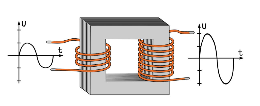
What’s worth distinguishing is scale. In utility contexts, “step-up transformer” usually means a generator step-up (GSU) unit feeding a transmission system. Dry-type step-up transformers operate well below that, in ranges such as:
- 480 V or 600 V → 4.16 kV
- 600 V → 13.8 kV
- 5 kV class → 15 kV, 25 kV, or 34.5 kV class
These are facility-level and equipment-level transformers, not transmission assets, and the application logic is different.
Where They’re Used
Distributed energy systems. The most common modern application is solar PV and battery energy storage. Inverters produce low-voltage output that has to be stepped up to medium voltage for facility or grid interconnection. The transformer sits directly between the power electronics and the electrical system, often inside a space-constrained enclosure. Harmonic loading from the inverter is non-trivial in these installations and typically drives a K-factor rating or equivalent derating in the specification.
Industrial systems with medium-voltage loads. When a facility has medium-voltage equipment — large motors, specialized process equipment — but is fed from a low-voltage system, stepping up locally near the load is often more practical than distributing medium voltage throughout the building. The transformer becomes part of a localized solution, usually installed in or near an electrical room.
On-site generation and microgrids. Generators, fuel cells, and microturbines typically produce power at low voltage. Connecting them to medium-voltage distribution requires a step-up transformer, and microgrids often involve several of these stepping up to a common bus. Voltage coordination across sources is the central design problem, and the transformer’s impedance and ratio are part of that picture.
Testing. OEM test cells are a clear example — facilities where medium-voltage equipment such as MV drives, motors, switchgear, and breakers must be tested in a lab environment that only has a low-voltage supply available. A step-up dry-type transformer feeds the test bus at the required MV level, often at non-standard ratios driven by the equipment under test rather than by distribution conventions.
What Actually Drives the Specification
The transformer is not fundamentally different in a step-up role. Its position in the system is. The table below summarizes how the specification logic shifts:
| Specification Factor | Conventional Step-Down | Step-Up Dry-Type |
|---|---|---|
| Typical voltage range | 15 kV / 25 kV / 34.5 kV class → 480 V or 600 V | 480 V / 600 V → 4.16 kV / 13.8 kV / up to 34.5 kV |
| Source of power | Utility (medium voltage) | Inverter, generator, fuel cell, or LV bus |
| Energized from | Primary (MV) side | Usually MV side, even though power flows from LV |
| Tap changer location | MV winding (standard) | MV winding — but taps may be reduced or omitted entirely |
| Voltage regulation source | Utility + transformer taps | Often handled upstream by the inverter or source |
| Harmonic loading | Typically modest | Significant in PV/BESS applications; K-factor often required |
| Role in the system | Passive distribution element | Active interface between generation and distribution |
| Protection coordination | Standard radial schemes | Bidirectional considerations, interconnection requirements |
| Voltage ratio drivers | Standard distribution levels | Inverter output, interconnection spec, facility bus |
Three decisions get missed most often.
Energization side vs. power flow direction
Power in a step-up application flows from low voltage to medium voltage. The transformer is not necessarily energized from that same side. In most installations tied to medium-voltage distribution, the transformer remains energized from the MV winding even though the source is on the LV side.
This matters because:
- The energized winding is treated as the primary for insulation and design purposes.
- BIL (Basic Impulse Level) and insulation requirements follow the energized winding.
- Tap changers are typically located on the energized side, where current is lower and the mechanical design is easier.
Confusing power flow with energization is one of the most common sources of specification error in step-up applications.
Tap location and whether taps are needed at all
Tap placement follows the energized side, not the higher voltage by default. If the transformer is energized from the medium-voltage side, taps go there.
The more interesting question is whether taps are needed in the first place. Many modern step-up applications are fed from regulated low-voltage sources — inverters, in particular — that hold their output voltage tightly. When the source already controls voltage, transformer taps add cost and complexity without solving a real problem. In these cases, a fixed-ratio transformer is often the right answer, with voltage adjustment handled upstream.
The decision comes down to a single question: where in the system does voltage variability actually live? Adjustment capability belongs there, not by default at the transformer.
Interaction with regulated sources
Inverters and similar power-electronic sources behave differently than utility feeds. They hold voltage stable at their own terminals across a range of operating conditions, but the transformer still influences what shows up at the medium-voltage bus through its impedance and turns ratio.
A typical example: during a sudden load step on the MV side, the inverter holds its LV output steady, but the voltage drop across the transformer impedance produces a transient sag at the MV bus that the inverter doesn’t see and can’t directly correct. Partial loading and harmonic-rich loads create similar effects in steady state. Coordination between the source and the transformer — not just sizing — is what determines whether the system runs cleanly.
System Position and Interface Effects
Step-up dry-type transformers usually sit at a boundary: between generation and distribution, or between LV equipment and an MV bus. That position has consequences beyond the transformer itself.
Protection coordination has to account for bidirectional considerations and, in grid-tied systems, utility interconnection requirements. Grounding configuration — Wye-Delta, Delta-Wye, or otherwise — is a real specification decision driven by the source characteristics and the downstream system, not a default. Energization sequences and switching procedures often differ from a standard step-down installation.
Voltage ratios, finally, tend to be driven by interface requirements rather than standard distribution levels. Matching an inverter’s output window, aligning with a facility bus, or meeting an interconnection spec can all push toward less conventional ratios and tighter tolerances than a typical step-down unit would carry.
Conclusion
The equipment is well understood. The application is where things go wrong. Specifying a step-up transformer the same way as a step-down unit — defaulting the energization side, placing taps by habit, ignoring how a regulated source changes the voltage control problem — produces issues that surface after commissioning, when they’re most expensive to fix.
Three questions, answered clearly up front, prevent most of them. Where is the transformer energized from? Where in the system does voltage variability actually live? What is the transformer being asked to do at the interface? When those are clear, the rest of the specification follows.
Transformer Paralleling: Principles and Practical Considerations
Operating transformers in parallel is a common way to increase capacity, build in redundancy, and stage capacity additions over time. Rather than relying on a single larger unit, multiple transformers supply a common bus and share the load.
The concept is straightforward. Execution is less so. Parallel operation depends on several parameters being aligned within tight limits, and small mismatches produce disproportionate problems — circulating currents, uneven loading, and accelerated insulation aging in the unit that ends up carrying more than its share. Paralleling should be treated as a verification-driven design decision, not a default configuration.
Core Requirements
Five parameters must be aligned:
- Voltage ratio must match within about 0.5%. Mismatches drive circulating currents because each transformer tries to impose a slightly different secondary voltage.
- Polarity must be identical. Opposite polarity creates a direct short circuit at the moment of energization.
- Phase sequence must be the same on both sides. A-B-C paralleled with A-C-B produces a bolted fault when the tie breaker closes.
- Vector group must match, or must produce the same phase displacement. A Dyn11 transformer cannot be paralleled with a Dyn1 unit — the 60° phase difference guarantees destructive circulating current.
- Percent impedance must be similar on a per-unit basis, typically within 7.5%. Transformers do not need identical kVA ratings to parallel, but their per-unit impedances must match. This parameter determines how load is actually divided.
How Load is Actually Sharing
Load divides between paralleled transformers in inverse proportion to per-unit impedance. The same bus voltage appears across both units, so the one with the smaller internal voltage drop pushes more current — the lower-impedance transformer carries more load.
A worked example makes the sensitivity clear. Two 1000 kVA transformers supply a 1500 kVA load. If both are rated at 5.75% impedance, each carries 750 kVA — clean 50/50 split. If one is at 5.5% and the other at 6.0% — a mismatch well within manufacturing tolerance — the lower-impedance unit carries 785 kVA and the other 715 kVA. That 5% overload at full system load is enough to matter for insulation life over time.
For transformers of different kVA ratings, proportional sharing requires equal per-unit impedances, not equal ohmic impedances. The common field error is comparing nameplate percentages without confirming both are referenced to their own kVA base. Two transformers with the same 5.75% nameplate value but different kVA ratings have different per-unit impedances on a common base, and they will not share proportionally.
Circulating Currents
Circulating currents flow between paralleled transformers through the loop formed by the secondary windings and the common bus. They contribute nothing to load delivery — they only add copper losses and heating in both units.
They come from three sources: voltage ratio mismatch, tap settings out of alignment, and phase angle discrepancies between vector groups.
The concerning feature is that they don’t appear in panel load readings. A technician measuring secondary current at the breakers sees normal load current. Inside each transformer, however, load current and circulating current are stacking — both units run hotter than the measurements suggest. This silently consumes the capacity headroom that paralleling was supposed to provide.
Tap Settings
All paralleled transformers must be on the same tap position. A single 2.5% tap step covers the entire typical voltage-ratio tolerance, so one tap out of alignment produces significant circulating current even in transformers that are otherwise identical.
This is where paralleled systems most commonly fail in service. A maintenance crew adjusts a tap to correct a low-voltage complaint at one panel, not recognizing that the other transformer supplies the same bus and now disagrees about secondary voltage. The result is exactly the silent circulating current described above.
The procedural rule is firm: any tap change on one paralleled transformer must be replicated on all others, and the match verified before re-energization.
Installation Details
Cable length and routing between each transformer and the common bus add impedance to each current path. Unequal runs produce unequal external impedance, and once that happens, load sharing no longer tracks transformer impedances alone — the cable becomes part of the equation.
The effect is most pronounced at low-voltage secondary levels, where conductor impedance is a meaningful fraction of total transformer impedance.
The rule is symmetrical routing: equal cable lengths, identical terminations, matching conductor arrangements. In retrofits where physical constraints force asymmetry, the imbalance should be measured at commissioning and, if significant, compensated through tap adjustment.
When to Parallel, When Not To
Paralleling makes sense when the load exceeds a single economically available transformer, when N+1 redundancy is required, or when capacity needs to be staged over time. When the units are specified together from the start — same manufacturer, matched impedances, identical vector groups — it’s often the right answer.
It becomes problematic when units weren’t designed to operate together. Mismatched impedances, different vector groups, incomplete nameplate data, or mixing older and newer designs all push the system toward the failure mode where everything appears to work at commissioning while circulating currents quietly consume insulation life. In those cases, a single appropriately sized replacement is usually more reliable and, over equipment lifetime, less expensive.
Commissioning
Verification matters more than design intent here. Before energization, confirm voltage ratio on each tap via turns ratio test, polarity on each bushing, phase rotation on both sides, tap position on all units, and vector group against nameplate.
After energization, measure load sharing under actual operating load. Circulating current, if present, shows up as a difference between measured secondary current and computed load current — worth looking for explicitly rather than assuming its absence.
Conclusion
Transformer paralleling works reliably when the underlying requirements are met. The failure mode is not dramatic. It’s a slow, invisible cost paid in copper losses, thermal aging, and lost capacity headroom — exactly the resources paralleling was supposed to add.
Most problems trace to small mismatches: half a percent on voltage ratio, one tap out of alignment, a few percent on impedance. The remedy is the same in every case. Verify at every stage. Match what the design actually requires rather than what looks close enough on the nameplates. Treat every tap change on a paralleled transformer as a change to the whole system.
Partial Discharge in Dry-Type Transformers: Causes and Mitigation
Partial discharge (PD) is one of the most important indicators of insulation condition in dry type transformers. While it is often associated with factory testing, its real significance lies in what it reveals about long-term reliability.
Unlike catastrophic failures, partial discharge is a progressive phenomenon. It develops in localized regions of insulation and gradually degrades material over time. Left unaddressed, it leads to insulation breakdown, reduced service life, and eventual failure.
In dry type transformers, the absence of liquid insulation means that defects in solid insulation — voids, contamination, or surface irregularities — are directly exposed to electrical stress. Understanding and managing PD is therefore central to reliable operation.
This article looks at where PD originates, how it is detected, and how its impact can be mitigated.
What Is Partial Discharge?
Partial discharge is a localized dielectric breakdown that occurs within a portion of an insulation system without fully bridging the gap between conductors.
It develops where the local electric field exceeds the dielectric strength of the material at that point — typically at imperfections such as air voids, contamination, or material interfaces. PD appears in three main forms: internal discharge within insulation, surface discharge along insulation boundaries, and corona in high-field regions in air.
Individual discharge events are small, often measured in picocoulombs (pC). But they are repetitive, and their cumulative effect drives erosion, carbonization, and the formation of conductive paths through otherwise sound insulation.
Why Partial Discharge Matters
Each discharge event introduces localized thermal and chemical stress that gradually weakens the dielectric. Over time this produces erosion, tracking, and electrical treeing — branching conductive channels that eat into the insulation until breakdown occurs.
In the early stages, a transformer with active PD operates normally. Nothing in the load data or thermal readings suggests a problem. What is actually happening is that the insulation margin is quietly shrinking. For this reason, PD is best understood as an early indicator of insulation degradation rather than a fault condition in itself. By the time the symptoms become obvious, the margin is largely gone.
Dry Type vs Liquid-Filled Transformers
The impact of PD differs significantly between the two designs.
In liquid-filled transformers, discharge typically occurs within the insulating liquid or at liquid-solid interfaces. The liquid dissipates discharge energy and, when degraded, can be partially restored through filtration or degassing. The insulation system is, in a limited sense, serviceable.
Dry type transformers have no such buffer. Air may be present in the design, but the solid insulation absorbs the effects of any discharge. The air itself is not permanently damaged; the surrounding insulation is. The result is localized erosion, carbonization, and a progressive reduction in dielectric strength that cannot be reversed in service.
This is especially critical in cast coil transformers, where windings are encapsulated in epoxy. A void a few millimetres across inside the resin — often left behind from imperfect casting — can host recurring discharges for years, slowly carbonizing the cavity walls until a tracking path forms. The damage stays localized but never stops developing. This is why PD testing is a standard factory requirement for cast coil transformers: it is the only practical way to verify that those voids are either absent or small enough to remain inactive under service voltage.
Common Causes
Partial discharge is rarely random. It is associated with identifiable conditions that can be categorized into four groups.
Manufacturing defects are the primary cause. Voids in winding insulation, incomplete resin impregnation in vacuum pressure impregnated (VPI) or vacuum pressure encapsulated (VPE) designs, and imperfections in cast resin systems all create localized weak points where PD can initiate.
Installation and handling introduce their own risks. Mechanical damage during transport, dust and moisture contamination during a prolonged storage period, and poorly executed terminations can all create stress points that did not exist when the unit left the factory.
Environmental conditions influence PD behavior throughout service life. Moisture and airborne pollution promote surface discharge. High altitude reduces the dielectric strength of air and increases corona susceptibility — a consideration for installations above roughly 1000 m, where derating is typically required.
Electrical stress is the fourth contributor. Overvoltages, switching transients, and high dv/dt waveforms (rapid voltage rise rates) from variable frequency drives and other power electronics intensify local electric fields. A transformer specified for sinusoidal service can see materially higher PD activity when fed from a rectifier or inverter, even within nameplate limits.
Where PD Occurs
In dry type transformers, PD tends to develop in predictable locations. Internal voids within winding insulation are the classic site, as are interfaces between conductors and insulation, and boundaries where solid insulation meets air. Surface contamination can create conductive paths that support discharge along otherwise sound insulation surfaces.
Geometry matters as much as materials. Sharp edges and abrupt geometry changes concentrate electric fields and are disproportionately represented in PD activity. Reduced clearances, whether by original design or imposed by field conditions, have the same effect.
Detection Methods
PD detection falls into two broad categories: offline testing and online monitoring. Choosing between them — and between the specific techniques within each — depends on what question is being asked.
Offline testing is performed during factory acceptance and commissioning. The unit is energized under controlled conditions, typically at 1.8 times rated voltage per IEEE for cast resin designs, and PD levels are measured in picocoulombs. Acceptance limits vary by standard and by customer specification, but values below 10 pC at rated voltage are common targets for cast coil units. Offline testing establishes a baseline and verifies that the transformer meets specification before energization.
Online monitoring measures PD under actual operating conditions, including the switching transients and harmonic content the transformer actually sees. It can be continuous (permanent sensors feeding a monitoring system) or periodic (portable instruments used during scheduled inspections). Online data is noisier than offline data but more representative of real service stress.
Three detection techniques are in common use, and they are complementary rather than interchangeable:
- Electrical measurement is the most quantitative. It is the method specified in IEEE standards and is the right choice when a numerical result in pC is required.
- Acoustic detection uses sensors to pick up the pressure waves generated by discharge events. It is useful for locating the source of PD within a transformer enclosure and for monitoring in electrically noisy environments.
- Ultrasonic sensing detects discharge activity on external surfaces, bushings, and cable terminations, and is typically deployed during field inspections.
For a facility setting up a PD program, the practical starting point is a baseline measurement at commissioning using the method specified in the transformer’s factory test report, followed by periodic ultrasonic surveys during routine inspections. Continuous online monitoring is usually reserved for critical units where unplanned outage cost justifies the investment.
Interpreting Results
Absolute PD values are less useful than trends. A stable 10 pC reading consistent with factory results is generally unremarkable. A reading that has climbed from 10 pC to 25 pC over two inspection intervals is a clear signal of developing insulation issues, even if the absolute number is still low.
Environmental and operating conditions — temperature, humidity, voltage waveform, load — all influence measurements. Comparing readings taken under different conditions without normalizing for them will produce misleading conclusions.
The practical implication is that the first PD measurement on any given transformer is an investment in the baseline. Its value compounds over the life of the unit.
Mitigation
Managing PD addresses both its initiation and its progression.
At the design and manufacturing stage, the levers are well understood: high-quality insulation materials, controlled impregnation and casting processes, and attention to electric field control at edges, corners, and terminations. This is the stage at which most PD is either designed out or designed in.
During installation, the single most common field-induced PD source is cable routing. Cables installed too close to energized windings or buswork create local field intensification that was not present in the factory test configuration. The transformer can pass factory PD testing at 10 pC and show 50 pC in service purely because of how the cables were run. Maintaining the clearances specified in the installation drawings is not a suggestion; it is a precondition for the factory PD result to be meaningful in the field.
Terminations deserve the same discipline. A cable termination assembled in a clean, dust-free environment with properly seated stress relief components will behave very differently from one assembled on a dusty construction site at the end of a long shift.
In operation, environmental control and routine maintenance preserve the insulation. Cleaning to remove dust and contamination, inspection for moisture ingress, and periodic PD measurement collectively make the difference between a transformer that reaches its design life and one that does not.
Standards and Testing
PD testing for dry type transformers is defined in IEEE C57.12.91. These standards specify test procedures, test voltages, and acceptable PD levels for factory acceptance.
What they do not do is represent field conditions. A transformer that passes factory PD testing has demonstrated that its insulation system meets a controlled specification under controlled conditions. It has not demonstrated that it will see the same PD levels once installed in a specific building, fed from specific switchgear, terminated by a specific contractor, and operated in a specific environment.
Factory compliance is a baseline. Long-term performance is earned in installation and operation.
Conclusion
Partial discharge is not a fault. It is a signal — an early, quantifiable indicator of insulation degradation that begins long before any other symptom appears. In dry type transformers the signal is particularly important because the damage it reveals is cumulative and cannot be reversed.
Managing PD is not a test that gets passed once at the factory. It is a lifecycle discipline that starts with design, continues through installation, and persists through the service life of the transformer. Done well, it is one of the most reliable ways to protect insulation life and ensure the transformer delivers the service its nameplate promises.
Electrostatic Shields in Transformers: Solving Noise Issues
As electrical systems incorporate increasing levels of power electronics and sensitive digital equipment, power quality considerations have become more prominent in transformer applications. Variable frequency drives (VFDs), UPS systems, and switching power supplies introduce high-frequency noise and transient disturbances that were not significant in traditional linear systems.
Transformers are often assumed to provide complete electrical isolation. In practice, they do not block all forms of disturbance. High-frequency noise and transient voltages can couple from primary to secondary through inherent parasitic capacitance within the transformer.
Electrostatic shields are used to address this specific coupling mechanism. Their function is often misunderstood, leading to either over-specification or misapplication. Understanding how and when they are effective is essential for proper use.
The Problem: Capacitive Coupling in Transformers
Transformer operation is based on magnetic coupling between windings. This is the intended mechanism for power transfer. However, there is also an unintended electrical path created by parasitic capacitance within the transformer structure.
This parasitic capacitance exists both between the primary and secondary windings and between the windings and grounded components like the core and enclosure. Under normal 50/60 Hz operation, its effect is negligible. At higher frequencies, however, it becomes a viable path for current flow.
High-frequency voltage components—such as those generated by switching devices—can create displacement currents that pass through this capacitive path. As a result, noise and transient voltages can appear on the secondary side, even without a direct electrical connection.
This behavior is most relevant in systems with:
- VFDs producing high dv/dt (rapid voltage rise rate) switching waveforms
- UPS and rectifier-based systems
- Switching power supplies
- Exposure to utility switching or lightning-induced transients
In these environments, the transformer can unintentionally transmit common-mode noise from upstream sources to downstream equipment.
What Is an Electrostatic Shield?
An electrostatic shield is a grounded conductive barrier installed between the primary and secondary windings of a transformer.
In dry-type transformers, this is typically a thin layer of copper or aluminum foil placed between windings and bonded to ground through the transformer enclosure. The shield is positioned to intercept capacitive coupling paths without interfering with magnetic flux.
It is important to distinguish that the shield does not affect the transformer’s ability to transfer power. Magnetic coupling remains unchanged. The shield specifically targets the unintended capacitive coupling mechanism.
How Electrostatic Shields Work
High-frequency voltage changes on the primary winding create displacement currents that can pass through parasitic capacitance to the secondary. These currents effectively bypass the magnetic isolation provided by the transformer.
An electrostatic shield interrupts this path. When grounded, it acts as a reference plane that captures these displacement currents and diverts them directly to ground.
Instead of coupling to the secondary winding, the noise energy is dissipated through the grounding system. This reduces the magnitude of common-mode voltage and high-frequency disturbances appearing on the secondary.
The result is a cleaner electrical environment for downstream equipment, particularly where low noise levels are important.
The effectiveness of this mechanism depends entirely on proper grounding. Without a solid and continuous ground connection, the shield cannot perform its intended function.
Performance Expectations and Limitations
Electrostatic shields are effective at reducing capacitive coupling of high-frequency noise, but their capabilities are often overstated.
They can attenuate common-mode noise and reduce the transfer of fast transients between windings. This can improve the performance and reliability of sensitive loads by limiting unwanted electrical interference.
However, they do not eliminate all forms of disturbance. Electrostatic shields do not protect against large transient overvoltages, which must be addressed using surge protective devices. They also do not mitigate harmonic distortion or address differential-mode noise between conductors.
Performance varies depending on transformer design, construction, and frequency range. As such, electrostatic shielding should be viewed as a targeted mitigation measure rather than a complete isolation solution.
Grounding Considerations
Grounding is critical to the effectiveness of an electrostatic shield.
The shield must be solidly bonded to the transformer grounding system and properly integrated into the facility grounding network. In most dry-type designs, this connection is internal to the transformer, but overall system grounding quality still governs performance.
If grounding is poor, the shield may provide little benefit. In some cases, it can introduce unintended current paths or circulating noise currents, reducing overall system performance.
For installations involving sensitive electronic equipment, grounding design should be considered alongside transformer selection. Electrostatic shielding is only effective when the grounding system can properly carry and dissipate the intercepted noise currents.
When Electrostatic Shields Are Justified
Electrostatic shields are most valuable in applications where electrical noise or transient coupling can affect system performance.
This includes installations with sensitive electronic loads such as control systems, instrumentation, and communication equipment. Data centers and medical facilities are common examples where maintaining a stable electrical environment is critical.
Industrial facilities with a high concentration of VFDs or other switching devices may also benefit, particularly where common-mode noise propagation is a concern.
In contrast, for general-purpose distribution systems with predominantly linear loads and limited high-frequency noise sources, the benefit of an electrostatic shield is often minimal. In these cases, the additional feature may not provide measurable improvement.
The decision to include an electrostatic shield should therefore be based on the presence of noise sources and the sensitivity of connected equipment.
Interaction with Other Power Quality Measures
Electrostatic shields address only one aspect of power quality—capacitive coupling of high-frequency noise.
They are most effective when used in conjunction with other measures. Surge protective devices provide protection against transient overvoltages, while line reactors and filters address harmonic distortion and switching-related noise.
Proper grounding and bonding remain fundamental to overall system performance. These elements work together to manage different types of disturbances, and none should be considered a substitute for another.
Conclusion
Electrostatic shields are a focused design feature used to reduce the transfer of high-frequency noise and transient disturbances through transformers.
Their primary function is to interrupt capacitive coupling between windings, improving the electrical environment on the secondary side. This is particularly valuable in systems with sensitive electronic equipment or significant sources of switching noise.
However, electrostatic shields do not address all power quality issues. Their effectiveness depends on proper grounding, appropriate application, and coordination with other mitigation measures.
From an engineering standpoint, electrostatic shielding should be applied where it provides measurable benefit. It is not a default requirement, but a targeted solution for specific operating conditions.
Transformer Commissioning: Critical Checks for Safe Energization
Transformer commissioning is the final engineering control point before a unit is placed into service. It verifies installation quality, system compatibility, and equipment condition under controlled conditions before the unit goes live.
For dry-type transformers, commissioning takes on added importance. Without a liquid dielectric system, performance depends directly on insulation condition, cleanliness, mechanical integrity, and airflow. Errors that pass through commissioning go straight into service as operational risks.
A structured approach is essential. ANSI/IEEE C57.94 should be treated as the primary reference framework for installation, application, operation, and maintenance of dry-type transformers.
While IEEE standards provide the overarching methodology, commissioning must also be carried out in accordance with the manufacturer’s installation, operation, and maintenance (IOM) manual. Manufacturer guidance defines design-specific limits — such as clearances, torque requirements, environmental constraints, and testing boundaries — that govern safe energization. Where differences exist, manufacturer requirements should take precedence for that specific unit.
Commissioning as a System-Level Verification
Commissioning is not limited to the transformer itself. It verifies alignment between:
- Transformer design and system conditions
- Installation quality and environmental constraints
- Protection settings and fault study assumptions
This system-level perspective is critical. Many commissioning issues arise not from transformer defects, but from mismatches between equipment and application.
Documentation and Configuration Verification
Before field inspection or testing begins, the transformer must be validated against the design intent. This includes confirming:
- Rated voltage and system voltage alignment
- Tap position relative to expected operating voltage
- Vector group compatibility with system configuration
- Impedance consistency with protection coordination studies
Tap position deserves particular attention. Transformers are often shipped at nominal tap, but site voltage conditions may require adjustment. Incorrect taps can result in sustained overvoltage or undervoltage conditions that are not immediately obvious during energization.
Mechanical and Installation Verification
Mechanical condition directly influences dielectric performance and thermal behavior.
Commissioning should confirm that the installation supports both electrical integrity and cooling performance. This involves verifying:
- Adequate clearance for airflow and maintenance access
- Proper mounting, including use of anti-vibration isolation where required
- Removal of shipping restraints after final positioning
- Absence of debris, dust, or foreign objects inside the enclosure
Connection integrity is equally important. Bus and cable terminations must be:
- Clean and properly aligned
- Free of mechanical strain
- Tightened to specified torque values in accordance with the manufacturer’s IOM manual
Loose or misaligned connections are a primary source of localized heating and long-term insulation degradation.
Environmental and Pre-Energization Condition
Dry-type transformers are sensitive to environmental conditions at the time of energization. Commissioning should verify that:
- The installation environment is clean and dry
- Ventilation openings are unobstructed
- No condensation is present on windings or insulation surfaces
- Room ventilation or HVAC capacity is sufficient for heat removal
If the transformer has been stored or exposed to humidity, insulation condition must be verified prior to energization. Moisture is one of the most significant risk factors for dielectric failure in dry-type units. If insulation resistance is below acceptable levels or moisture is suspected, controlled drying procedures should be completed before proceeding.
Storage duration is itself a risk factor. A transformer delivered last week and a transformer that has been sitting at a job site for six months represent very different commissioning cases. For units with extended storage, insulation resistance should be measured and trended over time before energization, not just spot-checked at commissioning.
Cold weather introduces additional constraints. Where applicable, controlled warm-up procedures should be followed to prevent differential thermal expansion between conductors and insulation systems.
Electrical Testing
Field testing provides objective confirmation that the transformer is suitable for service and establishes a baseline for future condition assessment. Testing should align with IEEE guidance and manufacturer limits.
- Insulation Resistance (Megger): Confirms insulation integrity and dryness. Insulation resistance on the order of 2 MΩ per kV of rated voltage is commonly used as a reference for dry-type units under typical conditions. Measurements should be temperature-corrected to the manufacturer’s reference temperature (typically 20°C) and recorded for future trending.
- Winding Resistance: Identifies high-resistance joints, loose connections, or internal damage. Phase-to-phase consistency is key.
- Turns Ratio (TTR): Verifies transformation ratio and confirms correct tap settings.
- Polarity and Phase Relationship: Confirms proper phase rotation and compatibility with system connections or parallel operation.
- Applied Voltage (Hipot), where specified: Performed in accordance with IEEE guidance and limited to manufacturer-recommended levels to avoid overstressing insulation.
- Partial Discharge (PD), where specified: Particularly for cast coil and VPI/VPE units, field PD testing during commissioning establishes a baseline against the factory PD result and verifies that installation conditions — cable routing, clearances, terminations — have not introduced new discharge sources. See our article on Partial Discharge in Dry-Type Transformers for a fuller treatment.
Testing should be performed in a controlled and repeatable manner, with environmental conditions recorded to support future trending.
Auxiliary Systems and Functional Verification
Auxiliary systems must be fully operational prior to energization. Temperature monitoring systems should be verified for:
- Correct sensor placement
- Accurate signal transmission
- Proper alarm and trip setpoints
Where forced-air cooling is provided, fan operation and control logic must be confirmed. These systems are typically staged based on winding temperature and are critical for maintaining thermal limits under elevated loading.
Protection System Alignment
Transformer protection must be validated as part of commissioning, not assumed correct. This includes confirming:
- Relay settings align with coordination studies
- Trip functions operate correctly under simulated conditions
- Alarm and monitoring signals are correctly integrated
Improper protection configuration can result in either failure to trip under fault conditions or nuisance tripping during normal operation, including energization.
Pre-Energization Readiness
Prior to energization, the transformer must be in a verified, controlled state. This condition includes:
- All inspections and tests completed and reviewed
- Electrical connections confirmed and properly torqued
- Grounding system in place and verified
- Tap settings confirmed
- Enclosure secured with all panels in place
- No foreign material inside the unit
This stage represents the final opportunity to identify issues before exposure to system voltage.
Energization and Initial Operation
Energization should be performed from the source side with downstream load minimized where practical.
Transformer inrush current is expected and may reach several multiples of rated current. Protection systems must be configured to tolerate this transient condition.
During initial operation, attention should be given to:
- Acoustic behavior (abnormal noise or vibration)
- Electrical balance (voltage and current)
- Thermal response
- Any signs of insulation distress
Initial operation is not a passive step — it is part of commissioning and should be actively observed.
Documentation and Handover
Commissioning produces records that become the operational baseline for the transformer’s entire service life. The handover package should include:
- Signed and dated test reports for every test performed
- Configuration records (tap position, protection settings, sensor calibrations)
- Photographs of the nameplate, internal condition, and terminations
- A punch list of any deviations or items to be addressed post-commissioning
- The manufacturer’s IOM manual, kept on file for future reference
These documents are not paperwork. They are the reference baseline against which future testing, troubleshooting, and condition assessment will be performed. Without them, every future inspection is starting from scratch.
Who Performs Commissioning
Commissioning responsibility varies by project. For utility-scale and critical installations, NETA-certified field testing is often required by specification. For commercial and light-industrial installations, the installing contractor or a third-party testing agency typically performs commissioning. Manufacturer support — including factory test reports, IOM documentation, and direct engineering involvement — is available on most projects and can be especially valuable for unfamiliar designs or critical applications.
Common Commissioning Issues
Field experience shows that commissioning deficiencies are typically procedural rather than design-related. Common issues include:
- Incorrect tap configuration
- Loose or improperly torqued connections
- Contamination from construction debris
- Inadequate ventilation clearance
- Moisture ingress prior to energization
- Misaligned protection settings
These issues often do not cause immediate failure but create conditions for accelerated aging or intermittent operational problems.
Lifecycle Implications
Commissioning establishes the initial condition of the transformer’s insulation system, connections, and thermal environment. Deficiencies at this stage can lead to:
- Partial discharge due to contamination or moisture
- Thermal hotspots at high-resistance joints
- Reduced insulation life expectancy
- Increased maintenance requirements and reduced reliability
The cost of these consequences compounds over time. A loose connection caught at commissioning is a five-minute torque check. The same loose connection caught five years later, after thermal cycling has degraded the surrounding insulation, can be a winding replacement or a full unit failure. A properly commissioned transformer, by contrast, operates within its intended thermal and dielectric limits, supporting predictable long-term performance over a 25–30 year service life.
Conclusion
Transformer commissioning is a structured engineering process that validates installation, confirms system compatibility, and establishes a reliable baseline for operation.
For dry-type transformers, the absence of liquid insulation places greater emphasis on cleanliness, environmental control, and connection integrity. Following a disciplined approach aligned with ANSI/IEEE C57.94 — and grounded in manufacturer-specific IOM requirements — ensures that the transformer enters service under the correct conditions.
Commissioning is not simply about energizing equipment. It defines how that equipment will perform over its entire service life.
Rex Power Magnetics provides commissioning support for our dry-type transformers, including factory test reports, IOM documentation, and direct engineering involvement during field commissioning. Contact our engineering team for unit-specific commissioning guidance.
Dry-Type vs. Liquid-Filled Transformers: A Comprehensive Comparison
Transformers are central to electrical power systems, enabling voltage to be stepped up for transmission and stepped down for utilization. While the operating principle is consistent across designs, the method of insulation and cooling introduces meaningful differences in performance, installation, and lifecycle behavior.
The two dominant categories — dry-type and liquid-filled transformers — are not interchangeable. Each is optimized for specific environments, load profiles, and risk considerations. Selecting between them requires understanding how construction affects thermal performance, safety, maintenance, and long-term reliability.
Fundamental Difference: Insulation and Cooling Medium
The primary distinction lies in how insulation and cooling are achieved.
Dry-type transformers use solid insulation systems such as cast resin or VPI/VPE, with heat dissipated through air. Liquid-filled transformers use a dielectric fluid — mineral oil, natural ester, or synthetic ester — which provides both electrical insulation and effective heat transfer. This difference drives most of the practical trade-offs between the two designs.
Dry-Type Transformers
Dry-type transformers are constructed without liquid dielectric. Windings are insulated using solid materials, and cooling is achieved through natural convection or forced air. The absence of liquid eliminates spill risk and reduces fire propagation concerns, which makes them well suited to indoor installations and occupied spaces.
Air is a less effective cooling medium than liquids, which results in lower power density and greater sensitivity to ambient conditions. In practice, dry-type transformers are often larger for the same kVA rating and require careful attention to ventilation and enclosure design. They are commonly applied in commercial buildings, healthcare facilities, data centers, and indoor industrial environments where safety and accessibility are primary considerations.
Liquid-Filled Transformers
Liquid-filled transformers use a dielectric fluid to insulate internal components and remove heat. The fluid circulates through the transformer, transferring heat to radiators or tank surfaces where it is dissipated. At higher capacity ratings, this delivers higher power density, better overload capability, and more uniform winding temperatures — making them well suited to utility systems, renewable energy applications, and large outdoor industrial loads.
Fluid type matters significantly. Mineral oil is traditional and widely used but carries higher fire risk and environmental impact. Natural esters (such as FR3 from Cargill or BIOTEMP from ABB) are biodegradable with higher fire points. Synthetic esters are engineered for enhanced fire resistance in demanding environments. The increased use of ester-based fluids has expanded the range of applications where liquid-filled units can be installed, including some that were previously limited to dry-type designs.
Thermal, Efficiency, and Noise Performance
Liquid-filled transformers benefit from the higher heat capacity of dielectric fluids, allowing them to operate at higher loads while maintaining lower internal temperatures. Dry-type units, relying on air cooling, are more sensitive to ambient temperature and airflow — though properly engineered ventilation, enclosure design, and forced-air cooling can substantially close the gap.
At equivalent ratings, liquid-filled transformers typically have slightly lower no-load and load losses. Over a 25- to 30-year service life, this can translate to a measurable difference in energy cost, particularly for units operating near full load continuously. Dry-type designs using high-grade silicon steel or amorphous metal cores narrow this gap considerably.
Dry-type transformers can also produce slightly higher audible noise, since the surrounding liquid in a filled unit dampens core vibration. This is managed through enclosure design, mounting isolation, and lower flux density designs. For noise-sensitive installations, sound levels should be specified explicitly and verified against test reports per NEMA TR1 and IEEE C57.12.91.
Installation and Site Considerations
Installation requirements often influence transformer selection as much as electrical performance.
Dry-type transformers can typically be installed indoors and close to the load without fluid containment systems. They are also lighter than liquid-filled units of equivalent rating, which makes them the practical choice for upper-floor or rooftop installations where structural loading is constrained. NEC Article 450 governs transformer installation requirements in North America and specifies different clearance, ventilation, and fire separation rules for the two technologies.
Liquid-filled transformers have traditionally been installed outdoors or in dedicated enclosures due to fluid containment and fire protection requirements. High fire point ester fluids have expanded indoor installation options, but fluid management and containment remain important design considerations that add infrastructure cost and complexity not present in dry-type installations.
Maintenance and Lifecycle
Dry-type transformers generally require minimal routine maintenance — visual inspection, cleaning, ensuring adequate airflow, and periodic insulation resistance testing. There is no fluid to test, sample, or replace.
Liquid-filled transformers require periodic dielectric strength testing, moisture content analysis, and dissolved gas analysis (DGA). These diagnostics support predictive maintenance strategies, but they also add complexity, sampling requirements, and the need for trained personnel or third-party labs.
End-of-life considerations differ as well. Liquid-filled transformers require fluid disposal at decommissioning, with mineral oil units requiring particular care due to potential historical PCB contamination in pre-1980s equipment. Dry-type transformers have no fluid disposal requirement, simplifying end-of-life handling.
Safety and Environmental Considerations
Dry-type transformers eliminate liquid-related risks such as spills and leaks, and they generally present a lower fire load. This makes them well suited to occupied or sensitive environments — schools, hospitals, residential buildings, and indoor commercial spaces.
Modern ester-based fluids offer higher fire points (above 300°C for natural esters, compared to about 160°C for mineral oil), reduced flammability, and biodegradability — narrowing the safety gap with dry-type designs in many applications. For installations where any fluid presence is unacceptable — clean rooms, food processing, water treatment, occupied indoor environments — dry-type remains the only viable choice.
Cost: Initial vs. Lifecycle
At higher capacity ratings, typically above about 1,500 kVA, liquid-filled transformers often have a lower cost per kVA than dry-type units. At smaller ratings, the cost difference narrows or reverses, with dry-type sometimes being the more economical option upfront.
Beyond purchase price, lifecycle cost depends on installation infrastructure (containment, fire protection, ventilation), maintenance and diagnostic requirements, energy losses over the service life, and end-of-life handling. Dry-type transformers typically have lower maintenance and infrastructure costs across all ratings, and over a 25- to 30-year service life these savings frequently offset higher initial cost in indoor and occupied applications.
Application-Based Selection
Selection is driven by application constraints rather than preference for a specific technology.
Dry-type transformers are typically selected for indoor installations and occupied spaces, locations with strict fire safety requirements, upper-floor or weight-constrained installations, and any environment where fluid presence is unacceptable.
Liquid-filled transformers are generally preferred for higher-capacity systems above 1,500 kVA, outdoor installations with available containment infrastructure, applications requiring sustained overload capability, and installations where DGA-based predictive maintenance is part of the asset management strategy.
Why Customers Choose Dry-Type
For the applications dry-type transformers serve, several characteristics consistently drive selection:
- Safety in occupied spaces — no fluid means no spill risk, no leak containment, and lower fire load.
- Installation flexibility — indoor placement without containment systems, lighter weight, and simpler code compliance.
- Minimal maintenance — no fluid sampling, no DGA program, no end-of-life fluid disposal.
- Predictable long-term cost — lower infrastructure and ongoing maintenance combine to make dry-type the economical choice over the full lifecycle in most indoor applications.
- Custom engineering — dry-type designs lend themselves well to custom voltage configurations, special enclosures, and application-specific modifications.
Common Misconceptions
Several oversimplifications can lead to suboptimal decisions:
- Treating all liquid-filled transformers as equivalent despite significant differences in fluid type and fire performance.
- Assuming dry-type is always safer regardless of installation context.
- Assuming liquid-filled is always more efficient — efficiency depends on design quality and loading profile as much as insulation medium.
- Comparing initial cost without considering installation infrastructure, maintenance, and end-of-life requirements.
Conclusion
Dry-type and liquid-filled transformers represent two distinct approaches to insulation and cooling, each with clear advantages depending on the application. Dry-type offers simplicity, reduced environmental risk, and suitability for indoor and occupied installations. Liquid-filled provides superior thermal performance and higher power density at large ratings.
The right choice matches the operating environment, safety requirements, lifecycle expectations, and capacity rating of the specific application. For indoor installations, occupied spaces, and applications where low maintenance and installation simplicity matter, dry-type designs remain the leading choice.
Rex Power Magnetics designs and manufactures CSA-certified, UL-listed dry-type transformers from 50 VA to 15 MVA at our facility in Concord, Ontario. Whether your application calls for a standard distribution unit or a custom medium-voltage cast coil design, contact our engineering team to discuss whether dry-type is the right fit for your project.
How Transformers Are Constructed: A Deep Dive into the Process
Transformers are fundamental to electrical infrastructure, enabling efficient transmission and controlled distribution of power across virtually every sector. While the operating principle is well understood, the construction of a transformer is often less visible — and significantly more complex than it appears from the outside.
For dry-type transformers in particular, construction is not just a manufacturing process. It is a series of tightly controlled design and assembly decisions that determine thermal performance, mechanical strength, dielectric integrity, and long-term reliability.
This article walks through how a dry-type transformer is built — from core lamination to final test — and how each stage contributes to the performance of the finished unit.
Core Construction: Managing Magnetic Flux
The core provides a low-reluctance path for magnetic flux and is central to efficiency and loss performance. Most power and distribution transformers use laminated steel cores, typically grain-oriented silicon steel. Laminations are stacked rather than solid to reduce eddy current losses, which would otherwise scale with the conductive cross-section.
Core construction involves precision cutting of laminations, stacking in specific geometries (core-type or shell-type), and clamping to maintain mechanical rigidity and minimize vibration. Modern core-cutting techniques such as step-lap mitering and distributed gap cutting reduce magnetizing current, no-load losses, and noise — typically yielding a 5–10% reduction in no-load losses compared to traditional butt-lap construction.
Material selection also drives loss performance. Standard grain-oriented silicon steel (typically M3 or M4 grade) is common for general-purpose units. High-permeability grain-oriented steel (Hi-B grades) reduces no-load losses further. Amorphous metal cores can cut no-load losses by 60–70% compared to silicon steel and are increasingly specified for utility distribution transformers and DOE 2016-compliant designs.
In dry-type transformers, core assembly must also account for vibration and acoustic performance, since there is no oil medium to dampen sound. Core construction technique therefore directly affects the audible noise level of the finished unit.
Winding Construction: Electrical and Mechanical Design
Windings are where electrical energy is transferred, but they are also the most mechanically stressed components during operation and fault conditions. Conductors are typically copper or aluminum, selected based on cost, conductivity, weight, and thermal considerations.
The winding design must balance several competing requirements: electrical insulation between turns and layers, mechanical strength to withstand electromagnetic forces, and thermal pathways for heat dissipation.
Different winding configurations are selected based on voltage class and application:
- Layer windings — most common for low and medium voltage, with conductors wound in concentric layers separated by insulation.
- Disc windings — used for higher voltage applications, providing better impulse voltage distribution and short-circuit strength.
- Foil windings — used for low-voltage, high-current applications, with broad copper or aluminum foil providing excellent surge response and short-circuit strength.
From a construction standpoint, winding involves controlled tension during conductor placement, precise spacing and alignment, and integration of insulation materials between layers. Tension that varies during winding produces uneven layers, which create thermal hotspots and weak points under fault conditions.
Insulation Systems: Defining Dielectric Integrity
Insulation must withstand operating voltage, transient overvoltages, and thermal aging over the life of the unit. In dry-type transformers, three primary insulation approaches are used:
- VPI (Vacuum Pressure Impregnation) — coils are impregnated with polyester or epoxy resin under vacuum and pressure, producing a moisture-resistant winding suitable for most indoor environments.
- VPE (Vacuum Pressure Encapsulation) — similar to VPI but with multiple impregnation cycles, producing a thicker, more robust resin envelope for harsher environments.
- Cast resin — windings are fully encapsulated in epoxy resin within a mold, producing a sealed, void-free winding suitable for the most demanding environmental and dielectric conditions.
Each approach affects moisture resistance, mechanical rigidity, partial discharge performance, and long-term aging behavior.
The full dielectric system extends beyond the impregnation: turn-to-turn insulation, layer insulation, and phase-to-phase and phase-to-ground clearances all contribute. Insulation systems are also classified by thermal capability (Class B, F, H, or N), with Class H (180°C) and Class R (220°C) being typical for modern dry-type designs.
Thermal Design and Cooling
Transformer losses — both core losses and winding losses — are ultimately converted to heat. Managing that heat is a central part of construction.
In dry-type transformers, cooling is achieved through air. AN (air natural) cooling relies on convection and is typical for smaller units. AF (air forced) cooling uses fans to increase heat removal, often providing a 33% capacity increase over the AN rating in the same physical envelope.
Thermal performance is influenced by winding geometry and spacing, ventilation paths through the core and coils, and enclosure design. Unlike liquid-filled transformers, dry-type designs do not benefit from oil as a heat transfer medium, which makes physical layout and airflow management especially important during construction. Hotspot temperature rise — the difference between the hottest point in the winding and the average winding temperature — must be controlled through coil geometry rather than fluid circulation.
Mechanical Structure and Short-Circuit Strength
Mechanical integrity is often underappreciated until a fault occurs. During short circuits, windings are subjected to electromagnetic forces that can reach several hundred times normal operating force, capable of deforming or displacing windings if mechanical design is inadequate.
Construction must therefore include rigid clamping systems, axial and radial support structures, and reinforcement of winding assemblies. These elements maintain geometry under stress, preventing changes in impedance or insulation failure.
In dry-type transformers, mechanical strength is achieved through structural bracing, resin systems (in cast coil designs), and tight assembly tolerances. Short-circuit performance is verified through type testing per IEEE C57.12.90 or IEC 60076-5 — and is as much a function of construction quality as electrical design.
Assembly and Integration
Once core and windings are complete, the transformer is assembled into its final configuration. This includes mounting the core and coil assembly, installing the enclosure, integrating terminals and bus connections, and providing grounding and structural supports.
For dry-type transformers, enclosure selection is integrated at this stage and has direct implications for cooling and environmental protection. Common configurations include ventilated (NEMA 1), non-ventilated (NEMA 2), weatherproof (NEMA 3R), and stainless-steel marine-duty enclosures (NEMA 4X). Enclosure choice affects allowable temperature rise, environmental rating, and audible noise.
Fit and alignment during assembly are critical. Mechanical stress introduced during assembly can persist into service and affect long-term performance.
Testing and Quality Verification
Construction is validated through testing. Routine tests performed on every unit typically include ratio and polarity verification, impedance measurement, no-load and load loss measurement, insulation resistance, applied and induced voltage tests, and partial discharge testing for cast coil and VPI/VPE units.
Type tests — including short-circuit withstand, lightning impulse, and temperature rise — are performed on representative units to validate the design rather than every individual transformer.
Compliance with standards such as IEEE C57, NEMA ST-20, and IEC 60076 provides the framework for these evaluations. Customer-witnessed testing is often available on request and is common for utility, data center, and critical industrial applications.
Conclusion
Transformer construction is a coordinated process that brings together magnetic design, electrical performance, thermal management, and mechanical integrity. Each element — core, windings, insulation, cooling, and structure — contributes to how the transformer performs over its service life.
For dry-type transformers, where cooling and insulation are tied directly to physical construction, these relationships are especially important. A transformer is not defined solely by its ratings, but by how it is built to achieve them.
Rex Power Magnetics is a vertically integrated dry-type transformer manufacturer with in-house enclosure fabrication, powder coat painting, semi-automated coil winding, step-lap mitered and distributed-gap core cutting, resin impregnation, vacuum-pressure epoxy encapsulation, and cast coil manufacturing — all under one roof in Concord, Ontario. Every unit is tested in our CSA-certified on-site facility before it ships. Contact our engineering team to discuss your application.
Air Core vs. Iron Core Inductors: Top Key Differences
Inductors—often referred to as reactors in power system applications—are used to store energy in a magnetic field and control current flow. Their behavior is fundamentally shaped by the material used in the magnetic path.
In practical terms, most applications fall into two categories: air core and iron core (ferromagnetic core) designs. The distinction between them is not just material—it directly affects inductance stability, saturation behavior, losses, size, and suitability for specific electrical environments.
For engineers working in power systems, drives, and dry type transformer installations, understanding this distinction is essential for correct equipment selection and predictable performance.
Why Core Material Matters
Inductance depends on both geometry and magnetic permeability. Air has very low permeability, while iron-based materials significantly increase it. This allows iron core inductors to achieve higher inductance in a smaller physical space.
That advantage, however, introduces additional behaviors—most notably saturation and core losses—that do not exist in air core designs.
The selection of core material therefore becomes a trade-off between:
- Linearity and stability
- Size and inductance density
- Losses and thermal performance
This trade-off plays out differently in power systems compared to electronic circuits.
Air Core Reactors: Linear Performance Under All Conditions
Air core inductors (commonly called air core reactors in power applications) operate without magnetic material. The magnetic field is established entirely in air, resulting in highly predictable behavior.
Electrical Behavior
The defining characteristic of an air core reactor is its linearity. Inductance remains essentially constant across the full operating current range because there is no core to saturate.
This has several direct implications:
- No inductance collapse under fault or transient conditions
- Stable impedance under harmonic loading
- Predictable performance across a wide current range
In systems with significant waveform distortion or high peak currents, this stability is often the primary reason for selecting an air core design.
Losses and Thermal Performance
Air core reactors do not experience hysteresis or eddy current losses associated with magnetic materials. Losses are dominated by conductor (I²R) losses and stray effects.
Thermally, this shifts the design focus toward:
- Conductor sizing
- Cooling through natural or forced air
- Physical spacing to manage heat dissipation
Because there is no core to absorb or concentrate heat, the thermal design is closely tied to winding geometry and airflow.
Mechanical Considerations
In medium- and high-power applications, air core reactors must withstand significant electromagnetic forces, particularly during fault conditions. Mechanical integrity is achieved through:
Coil bracing systems
- Fiberglass or composite structural supports
- Careful control of winding spacing
This is a critical but often overlooked aspect of air core reactor design.
Typical Applications
Air core reactors are widely used where linearity and reliability under abnormal conditions are required. Common applications include:
- Harmonic filtering (especially with capacitor banks)
- Current limiting reactors
- Neutral grounding reactors
- Shunt reactors in transmission and distribution systems
In installations with nonlinear loads such as VFDs, air core reactors are often preferred because they maintain consistent impedance under harmonic conditions.
Iron Core Inductors: Compact and Inductance-Dense
Iron core inductors use ferromagnetic materials to concentrate magnetic flux, allowing significantly higher inductance for a given size.
This makes them well suited to applications where space, weight, and inductance density are primary constraints.
Electrical Behavior and Saturation
The defining limitation of iron core inductors is saturation. As current increases, the core approaches its magnetic limit, beyond which inductance decreases sharply.
This has several practical consequences:
- Reduced impedance at high current
- Loss of filtering effectiveness
- Increased current and thermal stress
Unlike air core designs, iron core inductors must be carefully sized to ensure operation remains within the linear region under both steady-state and transient conditions.
Core Losses
Iron core designs introduce additional loss mechanisms:
- Hysteresis losses due to magnetization cycles
- Eddy current losses within the core material
These losses increase with frequency and flux density, making core material selection (laminated steel vs ferrite vs powdered iron) an important design decision.
Thermal Implications
Because losses are generated in both the conductor and the core, thermal design must account for:
- Core heating
- Hot spot development
- Cooling effectiveness within a more compact structure
This can limit performance in higher-frequency or heavily distorted waveform environments.
Typical Applications
Iron core inductors are commonly used in applications where high inductance is required in a compact footprint, such as:
- DC link chokes
- Power supply filtering
- Motor drives (where current is controlled)
- Low-frequency filtering applications
They are generally preferred where operating conditions are well-defined and saturation can be avoided through design margin.
Air Core vs. Iron Core: Application-Driven Selection
The choice between air core and iron core designs is best understood in terms of application priorities.
Air core reactors are typically selected when:
- Current levels are high or highly variable
- Harmonic content is significant
- Linearity and predictability are critical
- Saturation cannot be tolerated
Iron core inductors are typically selected when:
- Space constraints are important
- High inductance is required in a compact design
- Operating current is controlled and predictable
- Efficiency at low frequency is a priority
This is not a matter of one being better than the other. Each is optimized for a different operating envelope.
Frequency and System Context
Frequency plays a central role in core selection.
At higher frequencies:
- Core losses increase significantly in iron materials
- Air core designs become more attractive despite larger size
At lower frequencies:
- Iron cores provide efficient inductance with manageable losses
- Air core designs may become physically large for equivalent inductance
In power systems operating at 50/60 Hz, both designs are used—but for different purposes. Air core reactors dominate in harmonic filtering and current limiting, while iron core inductors are more common in controlled, lower-distortion environments.
Relationship to Transformer Applications
Although this discussion focuses on inductors, the same core material principles apply to transformers.
Iron cores are used in power transformers to efficiently transfer energy at low frequency with high flux linkage. Air core transformers, by contrast, are limited to specialized high-frequency applications where core losses must be minimized.
This reinforces the broader principle: core material selection is fundamentally tied to frequency, efficiency, and linearity requirements.
Common Misinterpretations
Several oversimplifications frequently appear in practice:
- Assuming higher inductance always leads to better performance
- Ignoring saturation behavior in iron core designs
- Overlooking harmonic effects when selecting reactors
- Treating air core reactors as inefficient without considering application context
In reality, performance depends on how well the component matches the operating conditions—not on any single parameter.
Conclusion
The distinction between air core and iron core inductors is fundamentally a trade-off between linearity and inductance density.
Air core reactors provide stable, saturation-free performance and are well suited to harmonic-rich, high-current, and dynamic environments. Iron core inductors offer compact, high-inductance solutions but require careful control of operating conditions to avoid saturation and excessive losses.
For engineers working in power systems and dry type transformer applications, the correct choice depends on load characteristics, harmonic content, frequency, and physical constraints. Understanding these factors allows for more reliable designs and avoids performance issues that often only emerge under real operating conditions.