Understanding Short Circuit Testing of Transformers: A Step-by-Step Guide
Short circuit testing is one of the most important validation steps in transformer design and manufacturing. While routine electrical tests confirm ratio, polarity, and losses, short circuit testing evaluates how the transformer behaves under the most mechanically and thermally stressful conditions it will ever experience.
For dry-type transformers, this is particularly critical. Unlike liquid-filled units, where oil provides additional mechanical damping and cooling, dry type designs rely heavily on solid insulation systems and mechanical bracing to withstand fault forces. Short circuit testing therefore provides direct evidence that the transformer can survive real-world fault events without structural or insulation failure.
This article explains what short circuit testing is, what it verifies, and how it is performed, with a focus on practical interpretation for engineers and specifiers.
What Is Short Circuit Testing?
Short circuit testing is performed to verify that a transformer can withstand the mechanical and thermal stresses associated with external short circuits.
During a fault, very high currents flow through the windings. These currents produce two primary stresses:
- Electromagnetic forces, which act on the windings and can cause deformation or displacement
- Thermal stress, caused by rapid heating due to high current flow over a short duration
The purpose of the test is not to simulate system protection behavior, but to confirm that the transformer’s internal construction—conductors, insulation, spacers, clamping structure—can endure these stresses without damage.
Standards such as IEEE C57.12.90 and IEC 60076-5 define the requirements and acceptance criteria for short circuit withstand capability.
Why Short Circuit Testing Matters in Practice
Short circuit events are relatively rare, but when they occur, they impose extreme conditions. A transformer that cannot withstand these stresses may experience:
- Winding deformation or displacement
- Insulation cracking or breakdown
- Changes in impedance or losses
- Progressive failure after the event
One of the more challenging aspects of short circuit damage is that it is not always immediately catastrophic. A transformer may remain energized but with internal mechanical damage that leads to premature failure months or years later.
For this reason, short circuit withstand capability is a key indicator of mechanical robustness, not just electrical performance.
Types of Short Circuit Tests
Short circuit testing is typically categorized into two complementary evaluations: thermal withstand and dynamic (mechanical) withstand.
Thermal Withstand Capability
This aspect evaluates whether the transformer can handle the heating effect of fault current over time, typically on the order of 1–2 seconds depending on system protection clearing time.
The focus is on:
- Conductor temperature rise
- Insulation thermal limits
- Hot-spot behavior
Thermal withstand is largely a function of conductor size, material properties, and cooling characteristics.
Dynamic (Mechanical) Withstand Capability
This is often the more demanding requirement. It evaluates the transformer’s ability to withstand instantaneous electromagnetic forces during the first cycles of a fault.
These forces are proportional to the square of the current and depend on winding geometry. They can cause:
- Axial compression or expansion
- Radial forces (hoop stress)
- Movement between winding layers
Mechanical withstand is heavily influenced by:
- Winding support structure
- Bracing and clamping design
- Resin system (for cast coil designs)
- Manufacturing quality and consistency
Both thermal and dynamic capabilities must be satisfied for a transformer to be considered short circuit robust.
Step-by-Step Overview of Short Circuit Testing
Short circuit testing is typically performed in specialized high-power laboratories due to the extreme currents required. The general procedure follows a structured sequence.
1. Pre-Test Measurements
Before applying any fault conditions, baseline measurements are taken. These typically include:
- Winding resistance
- Impedance voltage
- No-load and load losses
These values establish a reference point for post-test comparison.
2. Test Setup
The transformer is connected to a high-current source, often through a generator and impedance network capable of delivering controlled short circuit current.
One winding is energized while the other is short-circuited. The configuration is selected to produce the most severe stress condition based on the transformer design.
Instrumentation is installed to measure:
- Current magnitude and waveform
- Voltage
- Mechanical response (in some advanced setups)
3. Application of Short Circuit Current
A controlled short circuit current is applied for a specified duration. This duration is typically aligned with standard fault clearing times, often around 0.5 to 2 seconds depending on the test objective.
The applied current level is based on the transformer’s rated short circuit withstand capability, which is derived from its impedance and system assumptions.
During this period:
- Peak asymmetrical current produces maximum mechanical stress
- RMS current contributes to thermal stress
4. Post-Test Measurements
After the test, the same measurements taken before the test are repeated. The key objective is to detect any changes that would indicate internal damage.
Critical comparisons include:
- Changes in impedance (can indicate winding movement)
- Changes in losses (may indicate localized damage)
- Changes in resistance (possible conductor deformation or connection issues)
5. Inspection and Evaluation
Depending on the test protocol, additional inspection may be performed, including:
- Visual inspection (where accessible)
- Partial discharge testing
- Insulation resistance or dielectric testing
Acceptance criteria are defined by applicable standards. In general, the transformer must show no significant deviation from pre-test values and no evidence of mechanical or insulation failure.
Interpreting Test Results
For engineers and specifiers, the key question is not how the test is performed, but what its successful completion represents.
A transformer that passes short circuit testing has demonstrated:
- Mechanical integrity of the winding system
- Adequate bracing and clamping design
- Stability of electrical characteristics under stress
However, it is important to distinguish between:
- Type-tested designs, where a representative unit has been tested
- Routine-tested units, where each manufactured transformer is not individually subjected to short circuit testing
Most transformers are not short circuit tested on a per-unit basis due to the destructive potential and cost of the test. Instead, compliance is demonstrated through design qualification and similarity.
Design Factors That Influence Short Circuit Strength
Short circuit performance is not a single parameter—it is the result of multiple design decisions working together. Key influencing factors include:
- Winding geometry (disc vs layer, axial spacing)
- Conductor type and mechanical support
- Clamping structure and rigidity
- Insulation system (particularly in cast resin vs VPI designs)
- Manufacturing tolerances and consistency
For dry type transformers, cast resin designs often provide strong mechanical encapsulation, while VPI/VPE designs rely more heavily on bracing and structural support.
Common Misunderstandings
Several misconceptions often appear in specifications and discussions:
- Assuming impedance alone defines short circuit strength
- Treating short circuit withstand as purely a thermal rating
- Assuming all transformers of similar rating have equivalent mechanical robustness
- Overlooking the difference between tested design and tested unit
Short circuit performance is fundamentally a mechanical design problem under electrical excitation, not just an electrical rating.
Practical Specification Guidance
When short circuit performance is important—which is the case in most medium-voltage applications—engineers should consider:
- Requiring compliance with IEEE or IEC short circuit withstand standards
- Confirming whether the design has been type tested
- Evaluating mechanical construction approach, not just electrical ratings
- Coordinating transformer impedance with system fault levels
In critical applications, additional documentation or test evidence may be warranted.
Conclusion
Short circuit testing is one of the clearest indicators of a transformer’s mechanical and thermal robustness. It validates that the unit can survive the most severe electrical stresses it is likely to encounter in service.
For dry type transformers, where mechanical integrity of the winding system is essential, this testing provides confidence that the design is not only electrically correct, but structurally sound.
Understanding how short circuit testing works—and what it actually proves—allows engineers to make more informed specification decisions and avoid relying on incomplete or oversimplified indicators of performance.
Understanding Transformer Nameplates: Key Specifications
Transformer nameplates are often treated as simple identification labels—useful for confirming voltage or kVA during installation. In practice, they are compact engineering specifications. Each value on the nameplate defines a boundary condition for how the transformer will perform electrically, thermally, and mechanically.
For dry-type transformers, this is particularly important. Their performance is closely tied to ambient conditions, enclosure selection, cooling method, and load characteristics. Interpreting the nameplate correctly is therefore not just a commissioning task, it is part of proper system design and specification.
Rated Power: Interpreting kVA in Context
The kVA rating defines the apparent power the transformer can deliver continuously under its rated conditions. Those conditions include rated voltage and frequency, standard ambient temperature, and adequate cooling.
In practice, those assumptions are not always met. Several factors commonly reduce usable capacity:
- Harmonic-producing loads (VFDs, UPS systems, rectifiers) increase internal heating
- Elevated ambient temperature reduces thermal margin
- High altitude reduces cooling effectiveness
- Enclosure restrictions limit airflow
As a result, the nameplate kVA should be interpreted as a thermal rating under defined conditions, not a guaranteed capacity under all operating scenarios.
Voltage Ratings and Tap Adjustments
Primary and secondary voltages establish how the transformer interfaces with the system. A typical nameplate might indicate 13.8 kV primary and 480Y/277 V secondary. These values also correspond to insulation design and operating limits.
Most dry type transformers include off-load taps to adjust the effective turns ratio. These are typically provided in small increments (e.g., ±2 × 2.5%) to compensate for supply variation.
In application, tap settings are often underappreciated. They should be selected based on expected system conditions, not left as a field correction. Persistent voltage issues are frequently traced back to incorrect tap positioning rather than upstream supply problems.
Frequency: A Core Design Constraint
Transformer cores are designed for a specific frequency, most commonly 60 Hz or 50 Hz. The relationship between voltage and frequency determines magnetic flux density in the core. If frequency decreases while voltage remains constant, flux increases and can push the core toward saturation.
This is why a 60 Hz transformer cannot be applied at 50 Hz at full voltage without review. Either voltage must be reduced, or the transformer must be derated. Frequency is therefore not just a nominal value—it is a fundamental design parameter.
Impedance: Fault Levels and Voltage Behavior
Transformer impedance is often discussed in terms of fault current, but its role is broader than that. It influences both short-circuit performance and voltage behavior under load.
From a fault perspective, higher impedance reduces available short-circuit current. This can ease equipment duty and support protection coordination.
From a voltage perspective, the situation is more nuanced. Voltage regulation depends on both the transformer impedance and the load power factor. A simplified relationship is:
%VR≈I⋅(Rcosϕ+Xsinϕ)
Because transformer impedance is predominantly reactive:
- At or near unity power factor, voltage drop is driven mainly by resistance and is typically modest
- At lagging power factor, the reactive component dominates and voltage drop increases
- At leading power factor, voltage rise can occur
This leads to an important clarification: higher impedance does not inherently mean poor voltage regulation. However, in most real installations—where loads are inductive—it does result in greater voltage drop.
In practice, impedance selection is a trade-off between:
- Fault current limitation
- Voltage performance under expected load conditions
- Temperature Rise and Insulation System
Temperature rise and insulation class are closely related but serve different purposes. Temperature rise defines how much hotter the winding operates above ambient at rated load, while insulation class defines the maximum temperature the insulation system can withstand.
For example, a transformer with a 150°C rise and 220°C insulation class includes thermal margin between operating conditions and material limits.
This has direct lifecycle implications. Lower temperature rise designs operate cooler and generally provide longer insulation life, while higher temperature rise designs are more compact and cost-effective but operate with less thermal margin. The selection is ultimately a balance between first cost and long-term reliability.
Cooling Class and Operational Dependence
Cooling class defines how heat is removed from the transformer. Air natural (AN) units rely on passive cooling, while air forced (AF) units use fans to increase capacity.
Where both are provided, the nameplate may show dual ratings—for example, a base AN rating and a higher AF rating. This introduces an operational consideration: the higher rating depends on active cooling systems.
In facilities where the AF rating is used continuously, fan performance becomes a reliability dependency. Loss of forced cooling is not just a minor issue—it may require immediate load reduction.
Winding Configuration and System Interaction
The winding configuration—delta, wye, or grounded wye—determines how the transformer interacts with the system.
This affects several behaviors simultaneously:
- Grounding method and system reference
- Fault current paths and protection response
- Harmonic performance, particularly triplen harmonics
For example, a delta winding can trap triplen harmonics, while a grounded wye provides a stable reference for system grounding. These are system-level considerations that extend beyond simple connection diagrams.
Basic Insulation Level (BIL)
BIL defines the transformer’s ability to withstand transient overvoltages such as lightning or switching surges. It is not related to continuous operating voltage but to impulse survivability.
This becomes particularly relevant in:
- Utility-connected systems
- Outdoor installations
- Locations with higher lightning exposure
BIL should be coordinated with system insulation levels and surge protection strategy to ensure consistent protection across equipment.
Enclosure Type and Thermal Impact
Enclosure selection is often driven by environmental requirements, but it also affects thermal performance. Ventilated enclosures allow better heat dissipation, while more protective enclosures can restrict airflow.
This creates a trade-off between:
- Environmental protection (moisture, dust, corrosion)
- Cooling effectiveness and thermal margin
As a result, enclosure type should be evaluated alongside loading and ambient conditions, not treated as a purely mechanical decision.
Standards and Compliance
Nameplates typically reference applicable standards such as IEEE, NEMA, CSA, or DOE efficiency requirements. These define the basis for testing, performance expectations, and regulatory compliance.
Verification of these standards during specification is important, particularly where jurisdictional requirements or efficiency mandates apply.
Identification and Traceability
Serial number and manufacturer information provide traceability to factory records, test data, and support documentation. Given the long service life of transformers, this information becomes increasingly important over time for maintenance and asset management.
Putting the Nameplate into Practice
Most issues related to transformer nameplates arise not from missing information, but from incomplete interpretation. Individual values are often read correctly but not considered together.
Typical examples include:
- Assuming kVA applies regardless of harmonic content or ambient conditions
- Evaluating impedance without considering load power factor
- Overlooking the operational implications of cooling method
- Treating tap settings as adjustments rather than design inputs
A transformer nameplate should be read as a coordinated set of constraints, not a list of independent values.
Conclusion
A transformer nameplate is a concise engineering specification that defines how the unit is intended to perform. For dry type transformers, its proper interpretation requires understanding how electrical, thermal, and environmental factors interact.
Used correctly, nameplate data supports better specification decisions, improved system performance, and more predictable long-term operation. Misinterpreted, it can lead to avoidable issues that only become visible after energization.
The difference lies not in the data itself, but in how it is applied.
Passive Harmonic Filters Explained: Improving Power Quality
Modern electrical systems increasingly rely on power electronic equipment such as variable frequency drives (VFDs), rectifiers, uninterruptible power supplies (UPS), and renewable energy inverters. While these technologies improve control and efficiency, they also introduce harmonic currents into the power system.
Harmonics distort the normally sinusoidal waveform of electrical current and voltage. If not properly managed, they can lead to overheating in transformers, nuisance tripping of protective devices, reduced system efficiency, and premature equipment failure. One of the most widely used solutions for controlling harmonics is the passive harmonic filter.
Passive harmonic filters use combinations of inductors, capacitors, and resistive elements to reduce harmonic distortion and improve overall power quality. This article explains how passive harmonic filters work, why they are used, and how they contribute to more reliable electrical systems.
Understanding Harmonics in Power Systems
In an ideal electrical system, current and voltage waveforms are sinusoidal. However, non-linear loads draw current in pulses rather than in a smooth waveform. This behavior produces harmonic currents at integer multiples of the fundamental frequency.
In North American systems operating at 60 Hz, common harmonic frequencies include:
- 180 Hz (3rd harmonic)
- 300 Hz (5th harmonic)
- 420 Hz (7th harmonic)
These harmonic currents circulate throughout the power system and interact with system impedance. The result can be voltage distortion, increased heating in conductors and transformers, and reduced system efficiency.
Controlling harmonic distortion is therefore essential to maintaining power quality.
What Is a Passive Harmonic Filter?
A passive harmonic filter is an electrical network designed to reduce harmonic distortion by providing a low-impedance path for specific harmonic frequencies. The filter is typically installed in parallel with the load and diverts harmonic currents away from the power system.
Passive filters are composed of combinations of:
- Inductors (reactors)
- Capacitors
- Sometimes damping resistors
These components are arranged so that the filter resonates at a specific harmonic frequency. When harmonic currents occur at that frequency, they are absorbed by the filter rather than flowing through the upstream power system.

Types of Passive Harmonic Filters
Several configurations of passive harmonic filters are used depending on the harmonic spectrum present in the system.
Single-Tuned Filters
Single-tuned filters are designed to target a specific harmonic frequency, such as the 5th or 7th harmonic. These filters use a series combination of inductance and capacitance tuned to the desired frequency.
Single-tuned filters are commonly used in industrial systems with predictable harmonic sources, such as six-pulse rectifiers or VFD installations.
High-Pass Filters
High-pass filters are designed to attenuate a broad range of higher-order harmonics rather than targeting a single frequency. These filters combine inductance, capacitance, and resistance to provide low impedance at higher harmonic frequencies.
They are often used in combination with single-tuned filters to address a wider harmonic spectrum.
Second-Order Filters
Second-order filters provide improved harmonic attenuation and are commonly used in systems where multiple harmonic frequencies must be controlled. These filters are designed with a specific damping characteristic to avoid excessive resonance.
How Passive Harmonic Filters Improve Power Quality
Passive harmonic filters contribute to improved system performance in several ways.
By diverting harmonic currents away from the main power distribution system, they reduce total harmonic distortion (THD) in both current and voltage waveforms. Lower harmonic distortion improves transformer performance and reduces heating in electrical equipment.
Passive filters can also improve system power factor. Because they incorporate capacitive elements, they may provide reactive power compensation that supports voltage stability.
Additionally, reducing harmonic distortion improves the performance of protective devices and minimizes interference with sensitive electronic equipment.
Typical Applications for Passive Harmonic Filters
Passive harmonic filters are widely used in industrial and commercial installations where harmonic-producing loads are present.
Common applications include:
- Variable frequency drive systems
- Industrial rectifiers
- Data centers and UPS systems
- Mining and heavy industrial processes
- Renewable energy installations
In many of these environments, harmonic levels must meet power quality standards such as those outlined in IEEE 519.
Passive Filters vs Active Harmonic Filters
Passive harmonic filters are one of several technologies used to manage harmonics. Another common approach involves active harmonic filters, which use power electronics to inject corrective currents into the system.
Passive filters differ in several important ways.
They are generally simpler and more cost-effective for applications where the harmonic spectrum is predictable. They also require less control complexity and have a proven track record in industrial environments.
However, passive filters are designed for specific harmonic frequencies. If system conditions change significantly, their effectiveness may be reduced. Active filters offer greater flexibility but at a higher cost and complexity.
Selecting the appropriate filtering approach depends on system requirements and harmonic characteristics.
Design Considerations for Passive Harmonic Filters
Proper filter design requires careful analysis of the electrical system. Factors such as system impedance, load characteristics, and harmonic spectrum must be considered.
One important concern is resonance. Improperly designed filters can interact with system capacitance or inductance, potentially amplifying certain harmonic frequencies instead of reducing them.
Engineers must therefore evaluate the system carefully before installing passive filters to ensure proper tuning and stable operation.
The Role of Reactors in Passive Filters
Reactors play a central role in passive harmonic filters by controlling current flow and defining the filter’s resonant frequency. Air core reactors are commonly used because they avoid magnetic saturation and maintain stable inductance even under high harmonic currents.
Proper reactor design ensures the filter performs consistently while withstanding the thermal and electrical stresses associated with harmonic currents.
Conclusion
As modern electrical systems incorporate more power electronic equipment, harmonic distortion has become an increasingly important concern. Passive harmonic filters provide a practical and reliable method for reducing harmonic currents and improving power quality.
By using carefully designed combinations of inductors, capacitors, and resistive elements, passive filters divert harmonic currents away from the electrical distribution system. The result is improved efficiency, reduced equipment stress, and more stable system operation.
When properly designed and applied, passive harmonic filters remain one of the most effective tools for managing harmonics in modern power systems.
VFD Variable Frequency Drives Explained: A Full Guide
Variable Frequency Drives (VFDs) are widely used in modern industrial and commercial power systems to control motor speed, improve process control, and reduce energy consumption. By adjusting the frequency and voltage supplied to a motor, VFDs enable precise speed regulation and improved operational efficiency.
However, VFDs also introduce electrical characteristics that can negatively affect the power system if not properly managed. These include harmonic distortion, electrical noise, and voltage stresses that can impact both equipment and system stability. For this reason, many installations incorporate drive isolation transformers to improve power quality, protect equipment, and ensure reliable operation. This article explains how VFDs work, the electrical challenges they introduce, and why drive isolation transformers are often an essential part of a well-designed system.
How Variable Frequency Drives Work
An electric motor’s speed is directly related to the frequency of the electrical power supplied to it. Traditional power systems supply motors with a fixed frequency—typically 60 Hz in North America—which means the motor operates at a constant speed.
A Variable Frequency Drive controls motor speed by converting fixed-frequency power into a variable-frequency output. The process occurs in three primary stages.
First, incoming AC power is converted into DC power using a rectifier. This stage typically uses diodes or controlled semiconductor devices to create a DC voltage from the incoming supply.
Second, the DC power is smoothed using capacitors or inductors in a DC bus section. This stage stabilizes the voltage and provides energy storage.
Finally, an inverter section converts the DC voltage back into AC power with a controllable frequency and voltage. By rapidly switching semiconductor devices, the inverter generates a waveform that allows the motor speed to be adjusted precisely.
While this conversion process enables efficient motor control, it also introduces electrical effects that must be managed.
 Electrical Challenges Introduced by VFDs
 Electrical Challenges Introduced by VFDs
Because VFDs use power electronic switching devices, they do not draw current in a smooth sinusoidal pattern. Instead, current is drawn in pulses, creating harmonic distortion in the electrical system.
Harmonics can increase heating in transformers, conductors, and other electrical equipment. They may also affect sensitive electronics and interfere with protection devices.
In addition to harmonics, VFD systems can introduce high-frequency electrical noise and voltage transients. These effects can propagate through the electrical distribution system, potentially affecting nearby equipment.
Another concern involves common-mode voltage and grounding behavior, which can create circulating currents and increase stress on insulation systems.
For these reasons, VFD installations often require additional equipment to ensure the electrical system remains stable and reliable.
What Is a Drive Isolation Transformer?
A drive isolation transformer is a transformer installed between the power source and the variable frequency drive. Its purpose is to electrically isolate the drive from the upstream power system while improving power quality and system stability.
Unlike standard distribution transformers, drive isolation transformers are specifically designed to support the electrical characteristics of power electronic loads. Their design may include specialized winding configurations and impedance characteristics that help manage harmonic currents and electrical noise.
Drive isolation transformers are commonly used in industrial motor control systems, HVAC applications, water treatment facilities, and other installations where VFDs are widely deployed.
Benefits of Using Isolation Transformers with VFDs
One of the primary advantages of a drive isolation transformer is electrical isolation. By separating the input and output circuits, the transformer prevents direct electrical coupling between the VFD and the upstream system. This isolation helps protect sensitive equipment from disturbances generated by the drive.
Another important benefit is improved harmonic performance. Certain transformer configurations, such as phase-shifting designs, can help reduce harmonic currents returning to the power system. By altering the phase relationship between currents, these transformers can partially cancel specific harmonic components.
Drive isolation transformers also help reduce electrical noise and common-mode disturbances. The transformer acts as a barrier that prevents high-frequency switching noise from propagating upstream through the electrical distribution system.
In many installations, isolation transformers also improve system grounding by establishing a stable neutral reference where required.
Transformer Configurations Used for VFD Applications
Drive isolation transformers are often designed with specific winding configurations that support harmonic mitigation and system grounding.
A common configuration is delta–wye, which provides electrical isolation while allowing the secondary neutral to be grounded. This configuration also blocks certain zero-sequence currents from propagating upstream.
In larger installations, phase-shifting transformers may be used in multi-pulse drive systems. These designs can significantly reduce harmonic distortion by shifting current waveforms relative to each other.
Transformer impedance may also be selected to provide additional current limiting and harmonic control.
When Isolation Transformers Are Recommended
While not every VFD installation requires an isolation transformer, there are many situations where they provide clear benefits.
Isolation transformers are commonly used when:
- Sensitive equipment shares the same electrical distribution system
- Harmonic levels must be controlled
- Electrical isolation is required for safety or system protection
- Grounding configuration needs to be modified
- Large or critical drives are installed in industrial systems
Engineering evaluation of the power system typically determines whether a drive isolation transformer is recommended.
Practical Considerations for Transformer Selection
Selecting a transformer for a VFD application involves more than simply matching kVA ratings. The transformer must be capable of handling harmonic currents, thermal loading, and electrical stresses associated with power electronic drives.
Design considerations may include insulation system selection, conductor sizing, thermal management, and impedance characteristics. In environments with high harmonic content, specialized designs may be used to reduce additional heating caused by harmonic currents.
Proper transformer sizing and design ensure reliable operation and long service life.
Conclusion
Variable Frequency Drives play a vital role in modern motor control systems, enabling improved efficiency and operational flexibility. However, the electrical characteristics of VFDs can introduce harmonics, electrical noise, and grounding challenges that affect overall power system performance.
Drive isolation transformers provide an effective solution by electrically isolating the drive, improving power quality, and protecting upstream equipment. When properly specified and applied, they become an important component of reliable and efficient VFD installations.
Understanding the role of isolation transformers helps ensure that VFD-based systems operate safely, efficiently, and with minimal impact on the broader electrical network.
How to Calculate Transformer Fault Current: Power System Design Considerations
A transformer fault current calculation is one of the first steps in short-circuit analysis. It affects equipment interrupting ratings, bus bracing, protection coordination, and arc-flash studies. In practical terms, the available short-circuit current is highest closest to the source transformer and decreases as conductor and upstream source impedance are added downstream.
For most facility-level work, the starting point is the transformer secondary terminals. From there, engineers adjust the result for feeder impedance, utility source strength, motor contribution, and system X/R ratio as needed. This article explains the basic formulas, shows worked examples, and highlights the design considerations that matter in real installations.
What Limits Fault Current at a Transformer
At the transformer secondary, the key limiting factor is the transformer’s percent impedance (%Z). Percent impedance is determined by short-circuiting the secondary and increasing primary voltage until full-load current flows; the required voltage, expressed as a percentage of rated voltage, is the transformer impedance. Lower %Z means higher available fault current.
This is why two transformers with the same kVA and secondary voltage can produce very different fault currents if their impedance values differ. It is also why transformer impedance is such an important specification for both protection and equipment rating.
The Basic Fault Current Formula
For a first-pass calculation at the transformer secondary terminals, the standard method is:
- Isc = Ifl / Zpu
Where:
- Isc = symmetrical RMS short-circuit current at the transformer terminals
- Ifl = transformer full-load current
- Zpu = transformer impedance in per-unit, equal to %Z divided by 100
This is the same approach used in common engineering references for transformer secondary fault current calculations.
Full-load current formulas
For a three-phase transformer: Ifl = (kVA x 1000) / (sqrt(3) x Vll)
For a single-phase transformer: Ifl = (kVA x 1000) / V
These are the same full-load current relationships used in standard short-circuit calculation guides.
A Combined Shortcut Formula
Combining full-load current and impedance into one expression gives a convenient shortcut.
For three-phase transformers: Isc = (kVA x 1000) / (sqrt(3) x Vll x Zpu)
For single-phase transformers: Isc = (kVA x 1000) / (V x Zpu)
These formulas calculate the symmetrical RMS fault current at the transformer terminals, assuming the transformer is the dominant source and upstream source impedance is not limiting.

Example 1: Three-Phase Transformer Fault Current Calculation
Assume:
- Transformer rating = 750 kVA
- Secondary voltage = 480 V
- Impedance = 5.75%
First calculate full-load current:
- Ifl = (750 x 1000) / (1.732 x 480) = approximately 902 A
Convert impedance to per-unit:
- Zpu = 5.75% = 0.0575
Now calculate fault current:
- Isc = 902 / 0.0575 = approximately 15,687 A
So the available symmetrical fault current at the transformer secondary terminals is about 15.7 kA. This is the same method presented in widely used transformer secondary fault current references.
Example 2: Single-Phase Transformer Fault Current Calculation
Assume:
- Transformer rating = 50 kVA
- Secondary voltage = 240 V
- Impedance = 4%
First calculate full-load current:
- Ifl = (50 x 1000) / 240 = approximately 208.3 A
Then convert impedance:
- Zpu = 4% = 0.04
Then fault current:
- Isc = 208.3 / 0.04 = approximately 5,208 A
The available symmetrical fault current at the transformer secondary is therefore about 5.2 kA.
What the Basic Formula Assumes
The simple transformer-only method is useful, but it makes assumptions. It assumes the fault is at the transformer secondary terminals, the utility source is strong enough that transformer impedance dominates, and the result needed is symmetrical RMS current rather than peak asymmetrical current. In real systems, conductor impedance downstream of the transformer and source impedance upstream both reduce the fault level.
This is why available fault current decreases as you move away from the transformer through feeders, panelboards, and branch circuits.
Including Feeder and Source Impedance
When the fault is not directly at the transformer terminals, or when utility source strength is limited, a more complete approach is needed. In per-unit form, the fault current depends on the transformer impedance plus the impedance of the path to the fault location.
In practical terms:
- Ztotal = Zsource + Ztransformer + Zconductors
Then:
- Ifault = V / Ztotal
Using the per-unit method simplifies this because transformer per-unit impedance remains the same when referred from one side to the other.
This is the preferred method for larger studies, especially when analyzing switchboards, MCCs, or faults at remote buses rather than directly at the transformer terminals. IEC 60909 is the widely recognized international framework for these broader short-circuit calculations.
Symmetrical vs. Asymmetrical Fault Current
The formulas above produce symmetrical RMS fault current, which is the normal starting point for equipment rating and coordination studies. However, the first few cycles of a real fault also include a DC offset, and that can produce a significantly higher peak asymmetrical current. The severity of that peak depends on system X/R ratio.
This matters because:
- Breakers and fuses must interrupt the available current safely
- Bus structures and transformer windings must withstand the mechanical forces produced by peak current
- Arc-flash studies often need more than the simple terminal fault current value
So while the basic transformer fault current calculation is essential, it is not always the last step in a full protection study.
How Transformer Size and %Z Affect Fault Current
Transformer fault current rises with higher kVA and falls with higher impedance. That means a larger transformer with low %Z can produce very high short-circuit current, while a smaller transformer or one with higher impedance will contribute less. Typical transformer percent impedance values vary by transformer class and rating, and that variation is one reason fault current can differ substantially between otherwise similar installations.
This is also where design tradeoffs appear. Higher impedance helps reduce available fault current, which can ease equipment duty requirements, but it also increases voltage drop and can affect regulation. Lower impedance improves regulation but raises short-circuit current.
Practical Design Considerations
A technically sound transformer fault current calculation should feed directly into design decisions. At a minimum, it should be checked against:
- Equipment short-circuit current ratings
- Protective device interrupting ratings
- Bus and panel withstand capability
- Arc-flash study assumptions
- Future system expansion plans
In practice, this means the “transformer terminal fault current” is the starting point, not the end of the process. Designers still need to evaluate what happens downstream and how the system may change over time.
Common Mistakes
Several recurring mistakes appear in field calculations:
- Using line-to-neutral voltage instead of line-to-line voltage for three-phase calculations
- Forgetting to convert %Z into per-unit
- Assuming the transformer-only calculation applies at downstream equipment
- Ignoring utility source impedance or feeder impedance when they are significant
- Treating symmetrical RMS current as if it were the same as asymmetrical peak duty
Avoiding these errors leads to more reliable equipment selection and safer protection coordination.
Conclusion
Transformer fault current calculation starts with three inputs: kVA, secondary voltage, and percent impedance. From those values, engineers can calculate the available symmetrical short-circuit current at the transformer terminals using straightforward formulas. That basic result is essential for breaker selection, coordination, SCCR review, and arc-flash analysis.
For more accurate system studies, upstream source impedance and downstream conductor impedance should be added using a per-unit or equivalent-impedance approach. That is where short-circuit analysis moves from a quick transformer calculation into full power system design.
Transformer Rating Explained: What You Need to Know About Transformer Capacity
When engineers, contractors, and facility teams discuss transformer “capacity,” they are usually referring to the transformer’s rating. In practice, that sounds simple: a 500 kVA transformer can supply 500 kVA of load. But the real meaning of transformer rating is more nuanced. Capacity is not just a nameplate number. It is the result of thermal limits, insulation capability, cooling conditions, voltage and current relationships, and the operating assumptions built into the design.
Misunderstanding transformer rating can lead to oversizing, unnecessary cost, poor efficiency at actual load, or more serious problems such as overheating, nuisance trips, shortened insulation life, and limited future flexibility. For dry type transformers in commercial and industrial systems, the topic is especially important because ambient conditions, enclosure selection, harmonic content, and installation constraints can materially affect real-world performance.
This article explains what transformer rating means, how it is established, and what engineers should evaluate when translating nameplate capacity into a reliable specification.
What Does Transformer Rating Actually Mean?
A transformer’s rating is the amount of load it can carry continuously under defined conditions without exceeding allowable temperature limits. The most familiar rating is expressed in kVA, which reflects apparent power rather than real power.
kVA = (√3 × V × I) / 1000
For single-phase transformers:
kVA = (V × I) / 1000
This is why transformer size is normally stated in kVA rather than kW. Transformers must carry current regardless of the downstream load power factor. The winding and insulation system experience heating based primarily on current and losses, not only on useful real power delivered to the load.
A 1000 kVA transformer, then, is not simply a device that can support “1000 units of power” in every situation. It is a transformer designed to deliver its rated apparent power continuously at its rated frequency and voltage, within its thermal class, when installed under the environmental and cooling conditions assumed by the manufacturer.
Why kVA is the Standard Capacity Measure?
Using kVA instead of kW avoids tying the transformer’s rating to the characteristics of the connected load. The transformer does not control load power factor; it must be capable of carrying the required current whether the load is resistive, inductive, or nonlinear.
For example, two facilities may each draw 800 A from a transformer at the same voltage, but their true power in kW may differ depending on power factor. From the transformer’s thermal perspective, the current is what matters most. That is why nameplate capacity is based on apparent power.
This distinction becomes even more important in facilities with variable frequency drives, UPS systems, rectifiers, or other electronic loads. In those applications, RMS current and harmonic content may stress the transformer more severely than the real power number alone would suggest.
Nameplate Rating is Tied to Specific Assumptions
Transformer ratings are not abstract. They are based on a set of design assumptions, including:
- Rated primary and secondary voltage
- System frequency
- Ambient temperature
- Cooling method
- Insulation system and temperature rise
- Altitude assumptions
- Enclosure configuration
- Continuous loading conditions
This matters because a transformer that is fully adequate on paper may not be adequate in the field if those assumptions are violated.
As an example, a dry type transformer rated for operation in a standard ambient may run materially hotter in a warm electrical room with poor ventilation. Likewise, a transformer applied to a heavily harmonic-rich load may experience additional heating not reflected by a basic linear-load assumption. In both cases, the nameplate kVA remains unchanged, but the usable capacity margin may not.
The thermal basis of transformer capacity
At the core of transformer rating is heat. Every transformer generates heat from two main sources:
- No-load losses, primarily core losses, which exist whenever the transformer is energized
- Load losses, primarily winding losses, which increase with current
As load increases, winding temperature rises. Insulation life is highly sensitive to temperature, so transformer designers establish a rating that keeps the hottest parts of the winding within allowable limits for the insulation system.
This is why transformer capacity is fundamentally a thermal capacity, not just an electrical one.
In dry type transformers, heat dissipation is strongly influenced by construction and airflow. Cast resin and VPI/VPE designs differ in how they handle heat transfer, contamination exposure, moisture resistance, and mechanical robustness, but all rely on staying within temperature limits to achieve intended service life.
Temperature Rise and Insulation Class
One of the most misunderstood aspects of transformer rating is the relationship between temperature rise and insulation class.
Temperature rise is the increase in winding temperature above ambient when operating at rated load. Insulation class reflects the thermal endurance capability of the insulation system.
These are related but not interchangeable. A transformer may use a higher-temperature insulation system than is strictly required for its rated temperature rise. That additional thermal margin can improve durability and overload resilience, even though the nameplate kVA stays the same.
For engineers, the practical point is this: two transformers with the same kVA rating are not necessarily equivalent in thermal design or expected longevity. Construction quality, cooling path, conductor design, and insulation margin all influence how comfortably the transformer carries its rated load over time.
Capacity is Not the Same as Future Flexibility
A common specification mistake is assuming that selecting a larger kVA transformer is always the safest choice. In reality, oversizing has trade-offs.
A larger transformer may provide more future load growth margin, but it can also:
- Increase first cost
- Increase no-load losses
- Take up more space
- Raise inrush and fault current implications
- Operate less efficiently at typical load if the actual demand remains well below nameplate
On the other hand, undersizing reduces flexibility and may leave little margin for ambient variation, harmonics, expansion, or temporary overload conditions.
The best rating is usually not the largest practical unit. It is the size that aligns with actual demand, realistic growth expectations, loading profile, system constraints, and thermal environment.
Load profile matters more than peak nameplate thinking
Transformer selection should be based on how the load behaves over time, not only on the largest connected load total. Facilities rarely operate all connected equipment at full demand simultaneously and continuously.
Important questions include:
- What is the expected continuous load?
- What is the demand profile over a day or shift?
- Are there high short-duration peaks?
- Is future growth planned, and on what timeline?
- Are loads linear or nonlinear?
- Is the transformer feeding process equipment, tenant distribution, HVAC, data infrastructure, or mixed building load?
A transformer that is adequate for intermittent peaks may not need to be sized to that peak as if it were continuous. Conversely, a transformer feeding continuous, heat-producing, harmonic-rich electronic loads may need more deliberate margin even when the arithmetic kVA seems acceptable.
In other words, capacity planning is partly about electrical calculation and partly about understanding how the facility actually operates.

Power Factor Affects kW Rather than Transformer kVA Rating
Because transformer rating is in kVA, engineers sometimes ask whether low power factor requires a larger transformer. The answer is effectively yes, but through the kVA relationship rather than by changing the transformer’s definition.
For a given real power requirement in kW, lower power factor means higher kVA demand:
kVA = kW / power factor
So if a load requires 400 kW:
- At 1.0 power factor, the apparent power is 400 kVA
- At 0.8 power factor, the apparent power is 500 kVA
The transformer must be sized for the apparent power and corresponding current. That is why facilities with poor power factor can consume transformer capacity faster than expected, even before considering losses elsewhere in the system.
Harmonics can Reduce Practical Usable Capacity
In modern facilities, transformer capacity cannot be evaluated correctly without considering harmonics. Nonlinear loads such as VFDs, switch-mode power supplies, UPS systems, and data-processing equipment distort current waveforms and create additional heating.
This added heating occurs in the windings and, depending on harmonic spectrum and design, may also increase stray losses. The result is that a transformer may reach thermal limits at a lower real load level than a simple sinusoidal calculation would suggest.
This does not mean every transformer must be derated automatically. It means harmonic content must be treated as a design input. In dry type applications, the practical questions are:
- What percentage of the load is nonlinear?
- What is the expected harmonic spectrum?
- Is a K-factor rated design needed?
- Is electrostatic shielding required?
- Is there adequate thermal margin for real operating conditions?
Where harmonic content is material, transformer “capacity” is no longer just a basic kVA selection exercise. It becomes a thermal and power quality exercise.
Ambient Temperature and Ventilation are Part of Capacity
Transformer nameplate capacity assumes a defined ambient environment. For dry type transformers, installation conditions can have a major effect on temperature rise.
A transformer installed in a cool, well-ventilated room may perform very differently from the same unit installed in a compact electrical closet, on a mezzanine with limited airflow, or near other heat-generating equipment.
This is one reason enclosure and room design should not be treated as secondary issues. Real transformer capacity depends partly on whether the heat can actually leave the unit and the room. Poor ventilation does not change the nameplate, but it can absolutely change the transformer’s operating temperature and life expectancy.
In practice, rating review should include:
- Ambient design temperature
- Room heat rejection
- Clearance around the enclosure
- Adjacent heat sources
- Ventilated versus non-ventilated enclosure considerations
- Indoor versus outdoor exposure
- Altitude, where relevant
- Altitude can affect cooling performance
At higher elevations, lower air density reduces cooling effectiveness. Dry type transformers rely on air for heat removal, so altitude can influence usable loading unless the design already accounts for the installation condition.
This is often overlooked in early specification work. For projects in elevated locations, the transformer rating should be reviewed in the context of the site altitude rather than assumed to transfer directly from sea-level conditions.
Voltage Rating and Current Rating Must Both be Correct
Transformer capacity is often discussed only in kVA, but usable application also depends on matching voltage and current correctly.
A transformer may have the right kVA but still be wrong for the application if:
- The primary voltage does not match the service
- The secondary voltage does not match utilization equipment
- Tap range is insufficient for system variation
- The full-load current exceeds practical conductor or equipment coordination assumptions
- The impedance value creates undesirable voltage drop or fault current effects
Capacity is therefore only one part of transformer suitability. The rating discussion should always be integrated with the full electrical design context.
Impedance Influences How Capacity Behaves in the System
Although impedance does not change the nameplate kVA rating, it affects how the transformer performs under load and fault conditions.
Higher impedance generally reduces available fault current but can increase voltage drop under load. Lower impedance can improve voltage regulation but increase downstream fault duty.
This is important because engineers sometimes focus on kVA alone when comparing options. Two transformers with the same rating may behave differently in the system if their impedance values differ. That can influence motor starting, coordination, available fault current, and voltage stability at the load.
A sound specification process therefore treats transformer rating, impedance, and expected loading behavior as connected issues rather than isolated data points.
Continuous Load vs. Occasional Overload
Many users assume that transformer nameplate capacity can be exceeded occasionally without concern. In reality, overload capability depends on transformer design, prior loading, ambient conditions, and duration.
Some temporary overload may be tolerable under certain circumstances, but it should not be treated as routine design capacity. Repeated or sustained overloading accelerates insulation aging and increases failure risk.
For dry type transformers, this is particularly important in facilities where load growth occurs gradually and operating teams do not notice that the transformer has become a chronic bottleneck. A unit may continue to operate for some time while running hotter than intended, but that does not mean the loading is acceptable from a reliability or lifecycle perspective.
How to Think about Capacity When Specifying a Dry Type Transformer
A practical transformer capacity review should go beyond “What kVA do I need today?” A better question is: What rating is appropriate for this load, in this environment, with this operating profile, and this level of future uncertainty?
A disciplined specification process should consider:
1. Actual calculated load
Start with realistic demand, not only connected load totals. Use the best available load data, diversity assumptions, and operating profile.
2. Nature of the load
Identify whether the transformer serves linear building load, motors, mixed occupancy, process equipment, or harmonic-rich electronic systems.
3. Duty cycle
Determine whether the load is continuous, cyclical, peaking, seasonal, or intermittent.
4. Thermal environment
Evaluate ambient temperature, ventilation, enclosure arrangement, and site conditions.
5. Future growth
Include credible expansion margin, but avoid excessive oversizing without justification.
6. Efficiency and losses
Consider both no-load and load losses in relation to the expected operating point.
7. Reliability expectations
Critical facilities may warrant more conservative thermal margin and closer attention to construction details, not just nominal kVA.
8. System interaction
Check impedance, fault current, voltage regulation, conductor sizing, and coordination with upstream and downstream equipment.
Common Misunderstandings about Transformer Capacity
Several recurring misconceptions lead to poor selections:
“A larger transformer is always safer”
Not necessarily. It may increase cost and losses without delivering meaningful operational benefit.
“kW and kVA are basically the same”
They are only the same at unity power factor. Transformer thermal loading is tied to apparent power and current.
“If the nameplate says 100%, the transformer can handle anything up to that number in any environment”
Only under the conditions assumed by the design and installation basis.
“Harmonics only matter in very specialized facilities”
Not anymore. Many ordinary commercial and industrial systems contain enough nonlinear load to warrant review.
“Capacity is just an electrical issue”
It is also a thermal, mechanical, environmental, and lifecycle issue.
The Lifecycle View of Transformer Rating
Transformer rating should be treated as a lifecycle decision, not just a procurement input. A transformer that appears adequate on day one may prove costly over time if the selection ignores actual load shape, ambient conditions, harmonics, or growth trajectory.
A well-chosen transformer rating supports:
- Stable operating temperature
- Expected insulation life
- Reasonable efficiency at actual load
- Better resilience to site conditions
- Reduced risk of premature replacement
- Fewer surprises during expansion or operational change
For dry type transformers, where installation environment and thermal behavior are especially important, capacity should be interpreted with discipline rather than as a simple catalog number.
Conclusion
Transformer rating is often described as capacity, but the term means more than a kVA label. It represents the amount of load a transformer can carry continuously under defined electrical and thermal conditions without exceeding its design limits. That rating is shaped by current, temperature rise, insulation system, cooling conditions, voltage, frequency, and application environment.
For engineers and specifiers, the key takeaway is straightforward: selecting transformer capacity is not only about matching a calculated kVA. It is about understanding how the transformer will operate in the real world. Load profile, harmonics, ambient temperature, ventilation, impedance, and future expansion all influence whether a given rating will perform as intended over the life of the installation.
The most reliable specifications are the ones that treat transformer capacity not as a single number, but as an engineering decision.
Transformer Fault Current Calculation Explained: Methods and Formulas
Understanding available fault current is essential for safe and reliable power system design. When a short circuit occurs, the magnitude of current that flows is largely determined by transformer impedance and system configuration. Performing a proper transformer fault current calculation ensures that protective devices are correctly rated and that equipment can withstand short-circuit conditions.
Engineers and electricians frequently need to calculate fault current at the secondary terminals of a transformer for equipment selection, breaker coordination, and arc-flash studies. This article explains how to calculate fault current for a transformer, outlines the governing formulas, and discusses practical considerations in real-world applications.
Why Transformer Fault Current Calculation Matters
Short-circuit current determines:
- Breaker interrupting rating requirements
- Busbar bracing and equipment withstand ratings
- Protection coordination settings
- Arc-flash energy levels
- Ground-fault protection behavior
If available fault current exceeds equipment ratings, catastrophic failure can occur during a fault event.
Because transformers are often the primary source of fault current in industrial and commercial facilities, accurate calculation is critical.
The Key Factor: Transformer Impedance
The most important parameter in transformer fault current calculation is percent impedance (%Z).
Percent impedance represents the voltage required to circulate full-load current under short-circuit conditions. It effectively limits the maximum short-circuit current the transformer can deliver.
- Lower impedance → Higher fault current
- Higher impedance → Lower fault current
This inverse relationship forms the basis of the calculation.
Basic Formula to Calculate Fault Current from a Transformer
The available symmetrical short-circuit current at the transformer secondary can be calculated using:

ISC = Short-circuit current
IFL = Full-load current
Zpu = Per-unit impedance (percent impedance ÷ 100)
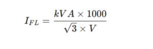
Step 1: Calculate Full-Load Current
For a three-phase transformer:
For single-phase:

Step 2: Apply Impedance

Example: Transformer Fault Current Calculation
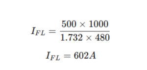
Given:
500 kVA transformer
480 V secondary
5.75% impedance
Step 1: Calculate Full-Load Current
Step 2: Convert Impedance to Per-Unit

Step 3: Calculate Fault Current
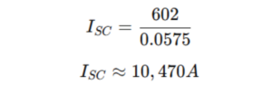
The available symmetrical fault current at the secondary terminals is approximately 10.5 kA.
Simplified Shortcut Formula

A commonly used shortcut for three-phase transformer fault current calculation is:
This combines both steps into a single expression.
What This Calculation Assumes
This method assumes:
- The transformer is the only source
- Infinite upstream source capacity
- Fault occurs at the secondary terminals
- Only transformer impedance limits current
In real systems, upstream utility impedance may further limit fault current.
Effect of Transformer Size and Impedance
Fault current increases when:
- Transformer kVA increases
- Percent impedance decreases
For example:
A 1500 kVA transformer with 5% impedance will produce significantly higher fault current than a 500 kVA transformer with 6% impedance.
This is why specifying impedance is a critical design decision. Higher impedance reduces fault current but increases voltage drop.
Calculating Fault Current on the Primary Side
To calculate primary-side fault current:
- Determine secondary fault current
- Divide by the turns ratio (voltage ratio)
Alternatively, apply the same formula using primary voltage and kVA rating.
Asymmetrical Fault Current and X/R Ratio
The previous calculations provide symmetrical RMS fault current. However, the initial fault current contains a DC offset influenced by the transformer’s X/R ratio.
Higher X/R ratio results in:
- Greater peak current
- Higher mechanical stress
- Increased breaker duty
Protection engineers must consider asymmetrical current when selecting interrupting devices.
Transformer Contribution in Larger Systems
In systems with multiple transformers or generators, fault current contributions must be summed using per-unit system methods. The simple method shown above applies primarily to single-transformer secondary calculations.
Common Mistakes When Calculating Transformer Fault Current
Frequent errors include:
- Ignoring percent impedance
- Confusing percent impedance with voltage regulation
- Using line-to-neutral voltage instead of line-to-line
- Forgetting to convert percent impedance to per-unit
- Ignoring upstream source impedance
Accurate transformer fault current calculation requires careful attention to units and system configuration.
Practical Design Considerations
When performing transformer fault current calculations, engineers must also evaluate:
- Breaker interrupting ratings
- Bus short-circuit withstand ratings
- Arc-flash incident energy
- Grounding method
- Parallel transformer operation
Higher fault current increases equipment stress but may improve protection sensitivity. Proper system design balances these factors.
Conclusion
Transformer fault current calculation is a fundamental step in power system design. By using transformer kVA, voltage, and percent impedance, engineers can calculate fault current transformer contribution accurately and ensure equipment is properly rated.
Understanding how to calculate fault current for a transformer supports safe breaker selection, proper coordination, and reliable system performance.
Inside a Transformer: Key Components and How They Work
Transformers are often described as simple devices: coils of wire wrapped around a magnetic core. However, anyone who has worked with power systems knows that the reality is far more sophisticated. Understanding what is inside a power transformer is essential for engineers, electricians, and purchasers who want to evaluate performance, reliability, and application suitability.
From the magnetic core to the insulation system, each internal component plays a critical role in voltage transformation, thermal management, and long-term durability. This article explores what is inside a transformer, how its key components function, and why their design matters.
The Magnetic Core
At the heart of every transformer is the magnetic core. The core provides a low-reluctance path for magnetic flux and enables efficient energy transfer between windings.
Inside the transformer, the core is typically constructed from laminated silicon steel sheets. These laminations:
- Reduce eddy current losses
- Improve efficiency
- Limit heat generation
The core is designed to operate below magnetic saturation under normal conditions. If the core saturates, excessive magnetizing current and heating can occur.
In dry-type power transformers, the core is usually assembled in a stacked or wound configuration and mechanically secured to minimize vibration and noise.
Primary and Secondary Windings
The windings are the conductive coils that carry current and enable voltage transformation.
When examining what is inside a power transformer, the windings are among the most critical elements. They are carefully designed to:
- Withstand mechanical forces during short-circuit events
- Manage thermal stress
- Maintain proper insulation clearance
Windings may be made of copper or aluminum conductors, depending on design requirements. The arrangement of turns determines the voltage ratio, while conductor size determines current-carrying capacity.
The relationship between primary and secondary turns establishes the transformer’s turns ratio and output voltage.
Insulation System
The insulation system is one of the most important components inside the transformer. While the core and windings enable operation, insulation determines service life.
In dry-type transformers, insulation may include:
- High-temperature enamel coatings
- Nomex® or similar insulation materials
- Epoxy resin systems (cast coil designs)
- VPI/VPE resin impregnation
The insulation class (such as 220°C systems in modern dry-type designs) defines the maximum thermal capability. Higher insulation classes allow for lower temperature rise designs, which can improve longevity and reliability.
Insulation protects against:
- Electrical breakdown
- Partial discharge
- Thermal degradation
- Core Clamping Structure
Inside the transformer, the core must be mechanically secured. Clamping structures maintain structural integrity and prevent movement during energization and fault conditions.
This internal framework:
- Maintains alignment of laminations
- Reduces vibration and audible noise
- Supports short-circuit strength
Proper mechanical design is essential for long-term reliability.
Tap Connections
Many transformers include internal tap connections that allow adjustment of the turns ratio. Tap links are usually located on the high-voltage winding and may be configured for off-circuit adjustment.
These taps help compensate for:
- Supply voltage variation
- Load-related voltage drop
- System optimization
Tap positions are typically accessed externally but are electrically part of the internal winding structure.
Cooling and Airflow Paths
Thermal management is another critical consideration inside a transformer.
Dry-type transformers rely on:
- Natural air cooling (AN / ANN)
- Forced air cooling (AF / AFN)
Internal spacing between windings and structural components is carefully designed to allow proper airflow. Adequate cooling ensures insulation remains within its temperature limits under full load conditions.
Terminals and Internal Connections
Internal leads connect windings to external terminals. These conductors must be properly braced and insulated to withstand:
- Thermal cycling
- Mechanical stress
- Short-circuit forces
Connection integrity directly impacts reliability.
Differences Inside VPI/VPE vs. Cast Coil Transformers
While the basic components are similar, the internal construction differs between dry-type designs.
VPI / VPE Transformers
- Windings are vacuum pressure impregnated with resin
- Insulation penetrates deeply into the coil structure
- Typically use high-temperature insulation systems
- Offer good heat dissipation
- Cast Coil Transformers
- Windings are encapsulated in epoxy resin
- Provide enhanced environmental protection
- Offer superior resistance to moisture and contaminants
- May have greater mechanical rigidity
Understanding what is inside a transformer helps clarify why different designs are selected for different environments.
How the Components Work Together
Inside the transformer, all components function as a unified system:
- The core guides magnetic flux
- The windings transfer energy
- The insulation protects against failure
- The clamping system ensures mechanical integrity
- The cooling paths control temperature
If any one of these elements is compromised, transformer performance and lifespan can be affected.
Why Understanding Internal Construction Matters
Knowing what is inside a power transformer is not just academic. It influences:
- Application suitability
- Maintenance planning
- Failure analysis
- Specification development
- Purchasing decisions
Engineers who understand internal construction can better evaluate design quality and long-term performance expectations.
Conclusion
A transformer may appear simple from the outside, but inside a transformer is a carefully engineered system of magnetic, electrical, thermal, and mechanical components working together. From the laminated core and precision windings to the insulation system and cooling pathways, each element plays a vital role.
By understanding what is inside a power transformer, engineers and decision-makers can make informed choices that support safety, efficiency, and long-term reliability.
How to Calculate kVA for Transformer Sizing
Transformer sizing starts with one number: kVA. Get the kVA right and the transformer will run within its design limits for decades. Get it wrong and the consequences show up as overheating, accelerated insulation aging, or — in the opposite direction — wasted capital on capacity that never gets used.
The math itself is straightforward. Where most sizing errors happen isn’t in the calculation; it’s in mixing up single-phase and three-phase formulas, confusing line-to-line and line-to-neutral voltages, or stopping at the calculated number instead of accounting for the real-world factors that drive it higher. This article walks through the formulas, the worked examples, and the considerations that come after.
Why Transformers Are Rated in kVA, Not kW
kVA (kilovolt-amperes) is apparent power — the total power the transformer must actually carry, including both the real power that does useful work (kW) and the reactive power that supports magnetic fields in motors, transformers, and other inductive loads (kVAR).
Transformer heating is driven by voltage, current, and impedance. Power factor doesn’t enter the heating equation directly, which is why transformers are rated in kVA rather than kW. A transformer feeding a 50 kW load at 0.8 power factor has to handle the same current as one feeding a 62.5 kW load at unity power factor — and it’s the current that produces the heat.
This is why every sizing calculation works in kVA, and conversions from kW require accounting for power factor.
Single-Phase kVA Calculation
For single-phase systems:
Where V is voltage in volts and I is current in amperes. Dividing by 1,000 converts VA to kVA.
Example. A 240 V load drawing 100 A:
A transformer supplying this load must be rated at at least 24 kVA. In practice this would round up to the next standard size — typically 25 kVA for single-phase.
Three-Phase kVA Calculation
Three-phase systems carry power across three conductors, so the formula includes a √3 factor to account for the phase relationship:
Where V is line-to-line voltage, I is line current, and √3 ≈ 1.732.
Example. A 480 V three-phase load drawing 75 A:
Round up to the next standard size — 75 kVA in this case.
The most common error here is using line-to-neutral voltage (for example, 277 V on a 480Y/277 V system) instead of line-to-line. The formula assumes line-to-line; using line-to-neutral will produce a number that’s too low by a factor of √3 and undersize the transformer significantly.
Converting from kW to kVA
When the load is specified in real power (kW) and power factor is known:
Example. A load requiring 50 kW at 0.8 power factor:
Round up to the next standard size.
This conversion matters whenever load data comes from equipment nameplates or mechanical/electrical schedules that report kW rather than kVA. Motors in particular are typically specified in horsepower or kW with a separate power factor figure.
Sizing from Existing Equipment
When working from nameplate data on existing equipment, the process is the same calculation applied to the data on hand:
- Identify system type — single-phase or three-phase
- Confirm the voltage rating, and verify whether it’s line-to-line or line-to-neutral
- Read or measure the full-load current
- Apply the correct formula
The result is the load’s actual kVA demand. From there, transformer sizing follows.
Why Accurate Sizing Matters
The cost of getting kVA wrong shows up at both extremes.
Undersizing drives overheating, accelerated insulation aging, voltage drop under load, nuisance tripping, and ultimately premature failure. Transformer insulation life roughly halves for every 8°C of sustained operation above the rated temperature rise, so even modest chronic overload has a real and measurable cost.
Oversizing costs less in failure terms but more in capital and operating efficiency. Larger transformers carry higher no-load losses, which run continuously whether the transformer is loaded or not. They also tend to operate at a lower fraction of their rated capacity, where efficiency curves are less favorable. The unit costs more to buy, more to install, and slightly more to run.
The goal is to size the transformer to load the actual demand, plus appropriate margin for the factors below.
Beyond the Calculation
The kVA number is the starting point, not the answer. Several factors push the required size up:
- Ambient temperature above the standard 40°C rating reduces capacity
- Altitude above 1,000 m (3,300 ft) reduces capacity due to thinner air cooling less effectively
- Harmonic content from variable frequency drives, UPS systems, LED drivers, and switching power supplies adds losses that linear kVA doesn’t capture
- Future load growth should be planned for explicitly rather than discovered later
- Duty cycle — continuous loads stress the transformer differently than intermittent ones
- Impedance requirements driven by short-circuit and protection coordination
- Inrush current from motor starting or transformer energization
For harmonic-rich environments, a K-factor transformer (K-4, K-13, or higher depending on the load profile) may be required even when the linear kVA calculation is correct. This is not a substitute for proper sizing — it’s an additional specification on top of it.
Standard Transformer Sizes
After calculating required kVA, select the next standard size above the calculated value:
- Three-phase: 15, 30, 45, 75, 112.5, 150, 225, 300, 500, 750, 1000 kVA, and higher
- Single-phase: 5, 7.5, 15, 25, 37.5, 50, 75, 100, 167, 250, 333, 500 kVA, and higher
Selecting the next standard size up is the conservative default. A detailed engineering study can sometimes justify tighter margins, but that’s the exception rather than the rule.
Conclusion
Calculating kVA is straightforward arithmetic. Sizing a transformer correctly is calculation plus judgment — applying the right formula to clean inputs, then adjusting for the environmental and load factors that shift the answer in practice.
Most sizing errors trace back to one of three causes: using the wrong formula for the system type, confusing line-to-line and line-to-neutral voltages, or treating the calculated number as the final answer without accounting for harmonics, ambient conditions, or future load. When those three are handled cleanly, the transformer runs within its design limits and delivers the service life it was built for.
Transformer Taps and Tap Changers: How They Work and When to Use Them
Supply voltage is rarely exactly what the nameplate says. Utility variation, feeder length, load growth, and seasonal changes all push the voltage at a facility’s electrical room away from the design point — sometimes by a few percent, sometimes by more. Transformer taps exist to compensate for that, allowing the turns ratio to be adjusted in fixed increments without replacing the equipment.
The concept is simple. The application is where things go wrong, usually because someone changes a tap to fix a symptom rather than a measured problem. This article covers what taps actually do, the difference between off-circuit and on-load tap changers, how to pick a tap position, and the mistakes that come up most often in dry-type installations.
What Taps Actually Do
Taps are connection points along a transformer winding that let the effective number of turns be changed. Selecting a different tap changes the turns ratio, which changes the secondary voltage proportionally.
The relationship is direct:
A tap that reduces primary turns increases the secondary voltage for a given input. A tap that increases primary turns decreases secondary voltage. This is the source of the most common point of confusion in tap selection — the relationship is inverse, and the nameplate doesn’t always make it obvious.
Taps are placed on the energized winding rather than always on the high-voltage side. In a conventional step-down transformer, those are the same thing — the primary is both energized and high voltage. In step-up applications, the energized side may still be the medium-voltage winding even though it’s now the secondary in power-flow terms. The current-carrying advantage of locating taps on the higher-voltage winding (lower current, smaller mechanical design) still applies in both cases.
Tap increments are typically:
- ±2.5% in single steps (most common on dry-type units)
- ±5% in single steps
- Combinations like four 2.5% taps spanning ±5%
Off-Circuit vs. On-Load Tap Changers
There are two fundamentally different ways to change a tap, and they serve different applications.
Off-circuit (de-energized) tap changers require the transformer to be fully de-energized before the tap can be moved. They are mechanical selectors operated by hand, usually through an external handle, and they cost very little to include in a transformer design. The trade-off is obvious — you can’t change the tap while the transformer is in service.
This is the standard configuration for dry-type transformers, distribution transformers, and most industrial power transformers. Off-circuit taps suit applications where voltage variation is slow and predictable, where tap changes happen during commissioning or after major load changes, and where the cost and complexity of an OLTC isn’t justified.
On-load tap changers (OLTC) can change taps while the transformer is energized and supplying load. They use a switching arrangement with transition resistors or reactors that briefly bridge two tap positions during the change, preventing both load interruption and contact arcing. The mechanism is significantly more complex — more moving parts, more wear, more maintenance.
OLTC is standard on utility transmission and large substation transformers, where voltage has to track load changes in real time and the transformer can’t be taken out of service for adjustments. It’s rare on dry-type units. The application typically doesn’t require dynamic regulation, and the added cost, mechanical complexity, and maintenance burden aren’t justified by the small operational benefit.
How to Actually Pick a Tap
Tap selection is a measurement-driven decision, not a guess. The procedure:
- Measure the actual secondary voltage under representative load conditions — not at no-load, and not based on what the utility reports at the meter
- Compare the measured value to the required nominal voltage for the connected equipment
- Calculate the percentage adjustment needed
- Select the tap position that compensates for the measured deviation
Worked example. A 480 V three-phase secondary measures 467 V under typical operating load. That’s roughly 2.7% low. A transformer with ±2.5% taps on the primary winding has a tap position that effectively reduces primary turns by 2.5%, which raises the secondary voltage by approximately that same percentage. Moving to that tap brings the measured secondary to about 479 V — within tolerance, without overshooting.
The key detail: changing a tap on the primary winding has an inverse effect on the secondary. Taking primary turns down raises secondary voltage. Tap nameplates typically show primary voltage values (e.g., “492 V,” “480 V,” “468 V” for a 480 V nominal primary), not the resulting secondary effect. Reading the nameplate correctly takes a moment of attention.
When Taps Get Used
Taps compensate for predictable voltage offsets, not for transient problems. The realistic use cases:
- Long feeder voltage drop. A facility at the end of a long utility run consistently sees lower-than-nominal supply voltage. Taps raise the secondary to match equipment requirements.
- Utility supply variation. Some service areas run consistently a few percent high or low. Taps shift the entire operating range back to nominal.
- Commissioning adjustment. Initial measurement after installation often reveals that actual voltage differs from the design assumption. Taps correct for the difference.
- Sustained load changes. Major load additions or removals shift the steady-state voltage profile. A tap change can restore the original operating point.
What taps don’t fix: harmonic distortion, transient sags or swells, brief utility events, or power quality problems generally. Taps adjust steady-state magnitude. Anything dynamic or non-fundamental requires a different solution.
Common Mistakes
A few patterns come up repeatedly in the field:
Changing taps without measurement. The most common error. Someone reports low voltage at a panel; the tap gets adjusted; the problem persists because the actual issue was a long branch circuit run, not the transformer supply. Tap adjustment should always follow a measurement that confirms the transformer secondary is actually off-nominal.
Failing to de-energize before an off-circuit tap change. Off-circuit tap changers are not rated to break load current. Operating one under load can cause arcing, contact damage, and in some cases a winding fault. Lockout/tagout is mandatory.
Forgetting that paralleled transformers must move together. If two transformers parallel into a common bus and one tap is changed without matching the other, circulating currents develop immediately. Any tap change on a paralleled system has to be replicated on all units.
Overcompensating for transient events. Tap changes correct steady-state offsets. They don’t fix events that come and go within minutes or hours.
Dry-Type Considerations
For dry-type transformers, tap adjustments happen rarely — usually at commissioning, occasionally after major load changes. Off-circuit construction means every adjustment requires de-energizing the unit, which in turn requires coordinating an outage. The procedural overhead alone keeps unnecessary changes in check.
Environmental factors deserve attention before the final tap is locked in. Ambient temperature, harmonic loading, and expected load growth all influence the right operating point. A tap selected during a cool commissioning visit may not be the right tap for the building once it’s at full occupancy and full summer ambient.
Tap changes on dry-type units should be performed only by qualified personnel with proper lockout/tagout in place and the position verified against the nameplate after the change.
Conclusion
Tap changers are a simple, durable solution to a real problem: matching transformer output to the voltage the system actually needs, rather than the voltage the design assumed. Off-circuit taps handle steady-state corrections at low cost; on-load tap changers handle dynamic regulation where the application demands it.
The mechanism works reliably when it’s used for what it’s designed for. Most tap-related problems trace back to changing a tap without measuring first, or to using taps to chase problems they were never meant to solve. Measure under load, change deliberately, verify the result — and the tap does its job for the life of the transformer.